In-depth analysis of high-end hardware heat sink technology: the integration and innovation of materials science, precision manufacturing and thermodynamic engineering
I. Introduction
In today's chip manufacturing process continues to approach the physical limit, the growth rate of heat flux per unit area of semiconductor devices is exceeding the carrying capacity of traditional heat dissipation architectures. While transistor density is climbing at the rate of Moore's Law, thermal management technology seems to be evolving at a completely different pace. This imbalance is elevating "heat dissipation" from an engineering auxiliary problem to a strategic bottleneck restricting the development of the entire electronics industry.
Hardware heat sinks - this seemingly mundane metal product labeled "traditional manufacturing" - are at the center of this thermal management revolution. From smart phone SoCs in consumer electronics, to inverter power modules in the industrial sector, to cabinet-level thermal management with power consumption exceeding 100 kilowatts in AI data centers, the material selection, structural design and manufacturing process of heat sinks are profoundly reshaping the underlying logic of the entire thermal management industry chain. This article will provide a systematic and in-depth analysis of the high-end hardware heat sinks technology system from six dimensions: material science, manufacturing process, thermodynamic design, thermal simulation technology, application scenarios and market trends.
Second, the material system: from single metal to multi-material collaboration
2.1 Performance spectrum of thermally conductive metal materials
The performance of a metal heat sink is based on the choice of material that conducts heat. In addition to the golden rule of electromagnetic wave propagation, heat dissipation engineers follow another set of simple and cruel physical laws - Fourier's law of heat conduction. According to this law, the thermal conductivity of a material (lambda, in W/(m · K)) directly determines its ability to transfer heat per unit of time.
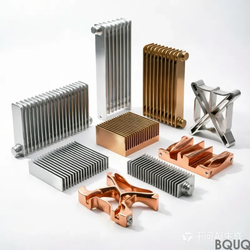
Copper and aluminum form the "Gemini" of metal heat sink materials. High-purity copper (industrial pure copper) has a thermal conductivity of about 400 W/(m · K), second only to silver, making it one of the most outstanding engineering metals in terms of thermal conductivity. The advantage of copper lies not only in thermal conductivity, but also in its excellent ductility and solderability - which allows two-phase heat transfer devices such as heat pipes and soaking plates to achieve efficient phase change heat transfer cycles with copper tubes as cavities. However, the density of copper is about 8.9 g/cm ³, which is more than three times that of aluminum, and the price is significantly higher. More importantly, in the atmospheric environment, the copper surface is easily oxidized to form a copper oxide/cuprous oxide layer, which not only darkens in appearance, but more importantly, its thermal conductivity plummets by more than one order of magnitude compared to pure copper, which will significantly deteriorate the interfacial heat transfer efficiency.
In contrast, aluminum alloy has won market dominance due to its comprehensive cost-effectiveness. 6063-T5 aluminum alloy maintains a thermal conductivity of about 200,237 W/(m · K) while taking into account both extrusion formability and mechanical strength. The density of aluminum is only 2.7 g/cm ³, which is about one-third that of copper. This property makes aluminum alloy an irreplaceable advantage in highly weight-sensitive fields such as mobile devices, avionics and new energy vehicles. The surface anodization treatment makes the resulting aluminum oxide film not only dense and corrosion-resistant, but also increases the surface thermal emissivity from the 0.10.2 level to more than 0.85 through a specific black oxidation process, improving the radiation heat dissipation efficiency.
However, the limitations of aluminum extrusion molding are equally significant: due to the fluidity limitations of aluminum during the extrusion process, there is an upper limit of about 1:18 to 1:20 on the ratio of fin thickness to height (i.e., slenderness ratio), which means that even with the most advanced extrusion dies, it is impossible to achieve infinitely dense fin arrangement within a limited height.
2.2 Frontier materials: graphene, carbon-based materials and composite structures
The thermal conductivity of traditional metallic materials is approaching its physical limit. In this context, advanced carbon-based materials stand out. The theoretical in-plane thermal conductivity of graphene is as high as 5,300 W/(m · K), which is about 13 times that of copper and more than 20 times that of aluminum. However, the large-scale preparation cost and reliability challenges of single-layer graphene in engineering practice have made it mainly stuck at the level of high-end flagship mobile phones and laboratory prototypes. On the more pragmatic path of industrialization, graphene has shown real value in the form of "composite materials". The composite material formed by adding graphene to the aluminum alloy radiator in a certain proportion shows that it can be cooled by 3 to 5 degrees Celsius more than pure aluminum alloy under the same conditions, and the quantitative production cost may even be lower than that of traditional aluminum alloy products.
The industrialization of artificial graphite film is more mature. The graphite heat dissipation film prepared by high temperature graphitization of polyimide (PI) film has an in-plane thermal conductivity of more than 1500 W/(m · K) and a thickness of 0.01mm. It has been widely used in the interior of smart phones and tablet computers to achieve rapid thermal diffusion of two-dimensional planes.
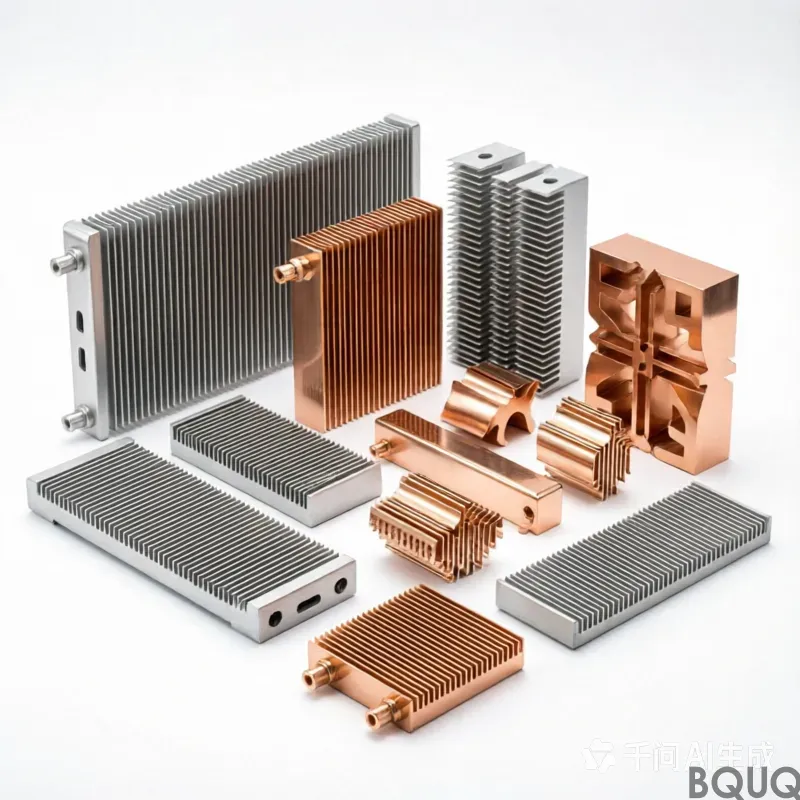
In actual product design, it is often difficult for a single material to meet the four requirements of "high thermal conductivity, low interfacial thermal resistance, lightweight, and low cost" at the same time, so multi-material composite solutions are becoming the mainstream direction. Copper-aluminum composite heat sinks - By embedding copper blocks or copper baseplates on the base of aluminum extrusion profiles, on the one hand, the high thermal conductivity of copper is used to quickly diffuse the peak heat of the chip from the local to the entire base. On the other hand, the lightweight and molding flexibility of aluminum are used to complete the construction of large-area heat dissipation fins, achieving a golden balance between cost, weight and performance.
III. Precision manufacturing processes: the technological leap from "extrusion" to "cutting"
The design value of a heat sink is essentially reflected in the mechanical distribution path of its material. The same material and design drawings, after the transformation of different manufacturing processes, the final heat dissipation performance may vary by more than 30%. The following is sorted out one by one from the key process paths.
Aluminum extrusion: This is the lowest cost and most widely used method for mass production of heat sinks. The aluminum alloy ingot is heated to 520~ 540 ° C, and it flows through an extrusion mold made of die steel under high pressure. It is rapidly cooled and solidified through the outlet die hole to generate a heat sink embryo with a continuous parallel fin structure. The advantage is that the mold cost is controllable, the cost of a single piece of finished product is low, and it is suitable for mass production. However, as mentioned earlier, its slenderness ratio is limited, which makes it difficult to obtain sufficient heat dissipation area in high power density applications, and it is difficult to cope with high TDP chips.
Shovel tooth cutting (also known as precision cutting or planing): This is a technical path that forces the "upper limit" of aluminum extrusion at the process level. The shovel tooth process uses high-precision planing machinery to cut a whole metal substrate, forming ultra-thin fins with tooth spacing as small as 0.5mm and tooth thickness as small as 0.3mm. Since the heat dissipation fins are integrally formed with the substrate, there is no brazing or fitting interface, so the contact thermal resistance of the shovel tooth radiator is completely eliminated. The measured data shows that the thermal resistance of the shovel tooth radiator is reduced by 15% to 20% compared with the tooth shaper radiator at the same volume, and the heat dissipation area is increased by 3 to 5 times compared with the traditional profile radiator. At present, this technology has been widely used in 5G base station AAU, new energy vehicle electronic control modules, and high-power industrial lighting.
Die-casting manufacturing: After the die-casting process melts the aluminum alloy ingot into a liquid state, it is filled with a precision metal mold at high pressure and high speed, and is formed by one-time die-casting with a die-casting machine. The die-casting process can make complex three-dimensional geometries that are difficult to process by traditional extrusion processes (such as special-shaped shells, integrated heat dissipation structures with mounting holes and positioning bosses), and has good mass production and controllable cost per piece. However, the early mold development cost is high, often hundreds of thousands to millions of yuan, and the development cycle is also long. And the melt may produce casting defects such as pores and cold partitions during the filling process, which affect the mechanical strength and local thermal conductivity uniformity.
Forging technology: Alloy materials with high aluminum content are pressed into molds through extremely high pressure (hot or cold forging). Forging processing allows the internal grain structure of the heat sink material to be compacted and aligned in a directional manner, resulting in higher tensile strength, smaller surface roughness and material uniformity. The product has a high aspect ratio fin structure. However, its die loss is serious, and the unit cost is much higher than that of the extrusion process. At present, it is mainly suitable for specific scenarios with extremely high requirements for mechanical properties and thermal conductivity.
CNC precision machining: In the finishing process, the CNC five-axis machining center is responsible for the grinding and polishing of the bottom plane of the heat sink, the drilling and tapping of the installation threaded hole, and the engraving of any complex process characteristics. Its accuracy can reach the micron level, the flatness can be controlled within 0.1mm, and the tooth pitch tolerance can reach ±0.05mm. However, the material removal rate per unit time is low, and the processing cost is significantly higher. It is usually only used for small batch and high-demand customization tasks such as aerospace and precision instruments.
From the perspective of production capacity and cost, it can be concluded that there are general stratifications: aluminum extrusion, die casting, and insertion riveting solutions occupy the mainstream market of low to medium power density; shovel cutting and forging solutions serve high power density and industrial and communication equipment that requires ultra-thin and high-density tooth groups; and one-piece CNC finishing is the "exclusive configuration" of scientific research or cutting-edge military industry.
IV. Thermodynamic design: fin, thermal resistance, duct and CFD simulation
4.1 Thermodynamic key parameters of heat sinks
The design of any heat sink essentially solves three coupled differential equations of heat transfer: heat conduction (through a metal body), convective heat transfer (through a fluid medium to remove heat from the surface of the fin), and radiative heat transfer (usually a small proportion, about 10% to 20%). In this physical architecture, there are several core engineering parameters that determine performance:
Thermal resistance (Rtheta, unit ℃/W) - This is the "first index" for electronic thermal engineers to screen and design heat sinks. The thermal path between the junction temperature of the chip and the ambient temperature can be modeled by a series-parallel thermal resistance network. A high-quality heat sink should make its own convective heat transfer thermal resistance as low as possible. Under natural cooling conditions, the thermal resistance can be controlled below 3 ℃/W; if combined with forced air cooling (i.e. fan), the industry's advanced level of thermal resistance can reach 0.5 ℃/W.
Fin morphological parameters - height, thickness, spacing, cross-sectional shape. If the spacing is too dense, the boundary lamination will inhibit the penetration depth of the air flow, resulting in a "dead gas zone" to reduce the convective heat transfer coefficient; if the spacing is too sparse, the total heat dissipation area is insufficient. The solution of the optimal gap is highly dependent on the airflow velocity, air physical properties and fin length.
4.2 CFD Thermal Simulation: From Empirical Design to Accurate Prediction
For a long time in the past, heat dissipation engineers relied on empirical formulas and trial and error verification in the warehouse. However, with the exponential growth of TDP of AI chips and 5G base stations, the power consumption of a single IC has broken through the one-dimensional channel of traditional air-cooled solutions, and the complex three-dimensional flow field and temperature field coupling problem must be solved by Computational Fluid Dynamics (CFD).
The most widely used thermal simulation software in the industry currently includes:
Ansys Icepak - Based on the Fluent Computational Fluid Dynamics kernel, designed for electronic thermal management. Its core strength lies in its ability to accurately model complex flow fields and surface geometries, and its integration into the ANSYS Workbench platform, which can be combined with the Mechanical Structural Analysis Module and the Maxwell Electromagnetic Analysis Module to realize three-field multi-physics field coupling simulation of electricity-heat-structure. In thermal analysis scenarios of automotive electronic surface controllers and irregular avionics components, Icepak's surface mesh adaptability is more accurate than structured mesh software.
Simcenter FloTHERM - As the world's first electronic heat dissipation simulation software, it has a market share of about 70% so far. FloTHERM uses a CFD solution algorithm specially optimized for electronic thermal management, and has a large built-in electronic component model library (including chip packaging models, heat sink models, PCB board models, etc.). Engineers can quickly drag and drop modeling to complete full-level thermal analysis from the component level to the system level, making it ideal for rapid thermal design iterations of consumer electronics products.
Yundao Intelligent Volta - as a purely domestic thermal simulation software, has developed rapidly in recent years and is accelerating to catch up with the simulation accuracy and ease of use of international mainstream tools.
From the actual engineering process, the typical design cycle is as follows: 3D CAD mechanical model introduction, boundary condition setting (ambient temperature, chip heat consumption, air volume and pressure curve) mesh division and solution, post-processing temperature cloud diagram and streamline analysis, size parameter iteration according to the simulation results, and finally get the optimal fin shape and spacing configuration.
V. Emerging application scenarios and market blue oceans
5.1 AI data center: fusion of liquid cooling and high-density metal heat sinks
The cabinet-level power consumption of AI servers is climbing exponentially. Taking the NVIDIA GB200/GB300 NVL72 system as an example, the thermal design power consumption of a single cabinet is as high as 130kW to 140kW, which far exceeds the physical bearing limit of traditional air-cooled cooling systems. In response to this trend, liquid cooling technology has begun to enter the large-scale deployment track. TrendForce data shows that the penetration rate of liquid cooling technology in AI data centers will rise sharply from 14% in 2024 to 33% in 2025.
However, the prediction of "liquid cooling replaces everything" is too one-sided. In the cold plate liquid cooling circuit, the cold plate (Cold Plate) is still a copper-based or aluminum-based hardware heat sink entity - it is contacted with the CPU/GPU chip through a thermally conductive interface material (TIM), and a series of microchannel flow paths are processed inside the cold water plate, and the coolant flows through these flow paths to carry heat away. The further microchannel cold plate and two-phase cold plate solutions are the ultimate challenges to the manufacturing process of heat sinks (micron-level channel processing, thermal interface bonding quality assurance, etc.). The "stage" of liquid cooling has instead raised the technical threshold of hardware heat sinks.
5.2 5G base stations and new energy vehicles
The single-station power consumption of 5G base stations is about 3 to 4 times that of 4G base stations. The outdoor environment of 5G base stations, the requirements of AAU natural heat dissipation and fanless passive heat dissipation have surged the demand for large-volume aluminum alloy radiators and shovel tooth radiators. As of the end of June 2025, the total number of domestic 5G base stations has reached 4.55 million, and the demand for 5G heat dissipation continues to rise. At the same time, in the field of new energy vehicles, IGBT power modules in inverters, on-board OBCs and motor controllers all require high-tooth density aluminum radiators to provide rapid heat removal, and with ultra-thin thermal interface materials to fill limited gaps.
5.3 Consumer Electronics: Technological Upgrade of Passive Cooling Solutions
In the field of high-performance smartphones, passive cooling solutions are constantly iterating. The combination of "VC soaking plate + graphite heat dissipation film + thermal interface material (TIM) " has become standard on flagship mobile phones. The iPhone 17 Pro released in 2025 used soaking plate VC for the first time, and the industry forecasts that global mobile VC sales will reach $2.776 billion by 2031. When VC and graphite membrane solutions are facing limits, micro-active cooling solutions such as micro-pump liquid cooling and thermoelectric cooling (TEC) are actively penetrating into thin and light devices.
Reliability Engineering: Failure Analysis and Thermal Interface Materials (TIM)
Reliability is the most underestimated but most lethal dimension in cooling system design. According to a large number of case studies by FAE (Field Application Engineer), poor contact of heat sinks or aging of thermal interface materials are the "hidden assassins" that lead to excessive temperature rise and early failure of MOSFET power tubes.
The Thermal Interface Material (TIM) is located in the filling gap between the heating device and the heat dissipation metal base, removing air (air thermal conductivity is only about 0.026 W/(m · K)), thus significantly reducing the contact thermal resistance.
In practical engineering, TIM faces two main types of aging failure mechanisms: thermal cycling aging leads to material hardening and loss of elasticity; and dry cracking caused by silicone oil migration and volatilization under long-term cold-heat alternation or high temperature conditions, and thermal resistance increases. Once the performance of TIM deteriorates, the chip junction temperature increases, the on-resistance (Rdson) increases, and the heat generation becomes more serious. The vicious cycle of thermal runaway can't be controlled.
More cutting-edge solutions involve the development of carbon-based high thermal conductivity TIM, as well as accelerated life testing and life prediction model methods studied by academic institutions such as Fudan University. International studies have also shown that the material thermal cycle pump-out effect of TIM is the core bottleneck leading to long-term reliability degradation. For industrial and automotive products, thermal cycle reliability verification must be carried out at the design stage.
VII. Market Prospects and Conclusions
The size of the global thermal solutions market is growing rapidly. According to professional organizations, the market will grow from $15.76 billion in 2025 to $17.06 billion in 2026, with a compound annual growth rate (CAGR) of 8.2%. By 2030, the total market volume is expected to reach $23.60 billion, and the CAGR will further expand to 8.5%. The core drivers driving this growth include: the surge in demand for advanced heat dissipation due to chip power density and miniaturization, the widespread adoption of liquid cooling solutions in AI cloud computing and high-performance computing, the entry of new material systems such as graphene and phase change materials into scale applications, and the trend towards the integration of predictive thermal management and intelligent heat dissipation systems.
Hardware heat sink - this seemingly ordinary metal component is undergoing a qualitative change from "supporting role" to "main engine". From the innovation of microstructure design of copper-aluminum composites, to the cutting process of shovel teeth breaking through the morphological limit of materials, from multi-physics simulation empowering precise thermal design, to tenaciously "holding the first door" in the extreme environment of AI server liquid cooling and 5G base station - the future of hardware heat sink technology is no longer a stock game of traditional manufacturing, but a new frontier of materials science and precision manufacturing engineering that crosses disciplinary boundaries. For all the engineering teams determined to establish a high ground in thermal management in the next generation of electronic devices, truly understanding and systematically optimizing the hardware heat sink technology system may be the first step in the strategy to determine whether heat flow can safely "go out".
BQUQ is a professional metal heat sink manufacturer, please send us drawings, and our company will quote you within 12 hours.