
Learn how heat sinks prevent thermal runaway in battery packs. Expert guide on design, materials, and tips for effective thermal management. Custom solutions available.
Heat Sinks for Battery Packs: Prevent Thermal Runaway
Thermal management is a critical aspect of battery pack design, especially as energy densities increase and applications demand higher power outputs. Without proper heat dissipation, battery cells can overheat, leading to thermal runaway—a dangerous chain reaction that can cause fires or explosions. Heat sinks serve as the frontline defense, channeling excess heat away from cells to maintain safe operating temperatures. This guide explores how heat sinks prevent thermal runaway in battery packs, covering design principles, material choices, and practical implementation tips.
Understanding Thermal Runaway in Battery Packs
Thermal runaway occurs when a battery cell experiences an internal short circuit, overcharging, or external heating, causing a rapid temperature rise. This heat triggers exothermic reactions within the cell, releasing more heat and potentially propagating to adjacent cells. The result can be catastrophic—fires, toxic gas release, and destruction of the pack. Common causes include:
Overcharging or over-discharging
Physical damage to cells
High ambient temperatures
Poor electrical connections leading to resistive heating
Manufacturing defects (e.g., metallic impurities)
Once a cell exceeds its critical temperature (typically 130–150°C for lithium-ion), the separator may melt, causing an internal short circuit. Heat sinks are designed to intercept this heat before it reaches dangerous levels.
The Role of Heat Sinks in Thermal Management
Heat sinks are passive or active cooling devices that absorb and dissipate heat from battery cells. In battery packs, they are typically placed between cells or on the pack casing. Their primary functions include:
Conducting heat away from cell surfaces
Increasing the surface area for convective cooling
Distributing heat evenly to avoid hot spots
Providing a pathway for heat to reach a cooling medium (air or liquid)
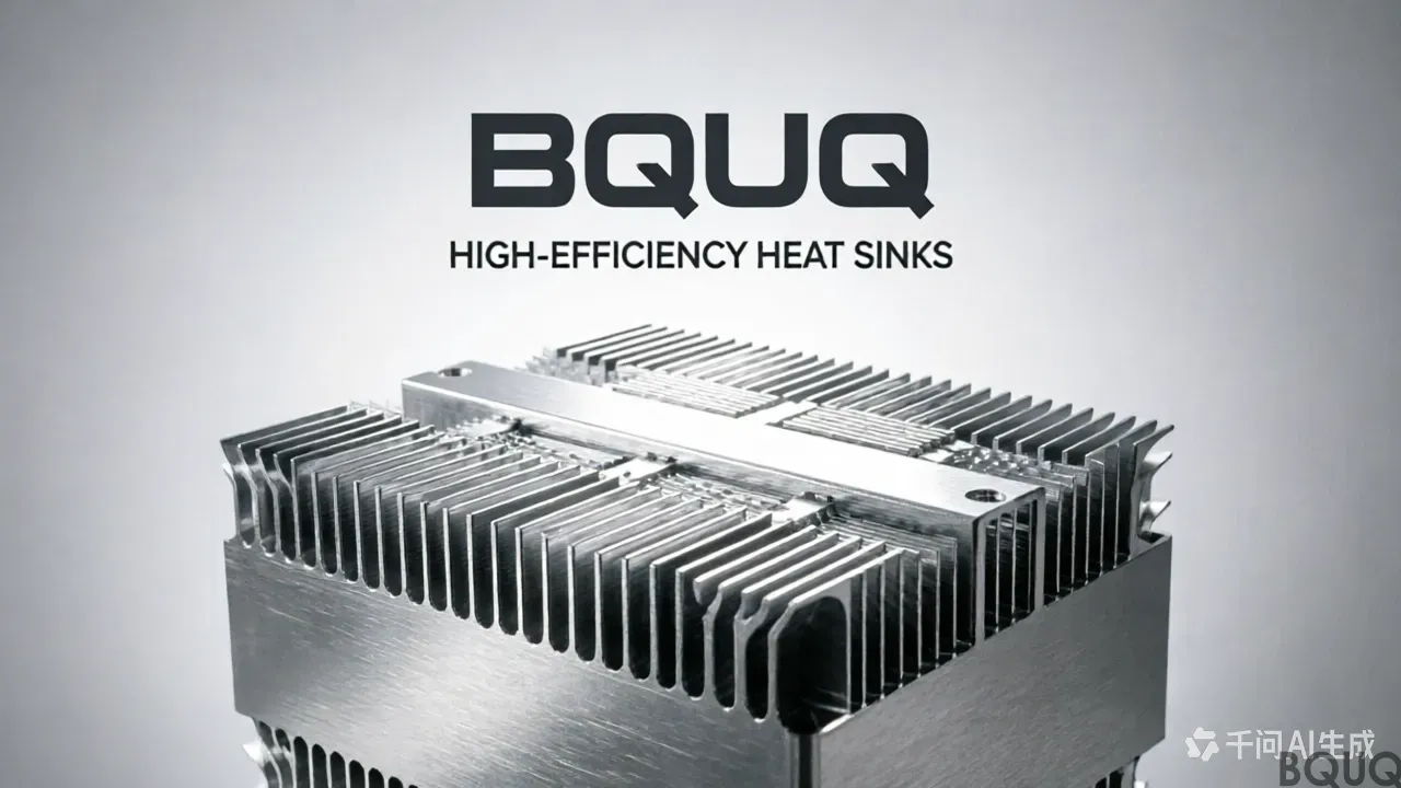
Common heat sink types for battery packs include extruded aluminum fins, stamped metal fins, and bonded fin assemblies. The choice depends on space constraints, weight, and thermal performance requirements.
Key Design Considerations for Battery Pack Heat Sinks
Material Selection
Aluminum is the most common material due to its high thermal conductivity (around 200 W/mK) and low cost. Copper offers higher conductivity (400 W/mK) but is heavier and more expensive. For weight-sensitive applications like electric vehicles, aluminum alloys (e.g., 6061 or 6063) are preferred. In some cases, graphite or composite materials may be used for enhanced heat spreading.
Fin Geometry and Density
Fins increase surface area for heat dissipation. Taller, thinner fins improve heat transfer but may require careful manufacturing to avoid bending. Fin density (fins per inch) must balance airflow resistance: too dense, and air cannot flow; too sparse, and surface area is wasted. A typical range is 8–12 fins per inch for natural convection and 12–16 for forced convection.
Thermal Interface Materials (TIMs)
Gaps between the heat sink and battery cells create thermal resistance. TIMs—such as thermal pads, greases, or phase-change materials—fill these gaps, improving heat transfer. For cylindrical cells, a conformal pad or epoxy is often used; for prismatic cells, a thin gap pad works well. The TIM must be electrically insulating to prevent short circuits.
Practical Tips for Implementing Heat Sinks
Correct Sizing
Calculate the total heat generation from the battery pack (based on current, internal resistance, and efficiency). Then select a heat sink with sufficient thermal resistance to keep cell temperatures below the maximum safe limit (usually 60°C for lithium-ion). Use the formula: Q = ΔT / R_th, where Q is heat load, ΔT is temperature rise, and R_th is thermal resistance of the heat sink.
Mounting and Contact
Ensure even pressure between cells and heat sink. Use clamping mechanisms or compression pads to maintain consistent contact. Avoid point loads that can damage cells. For cylindrical cells, a heat sink with a curved surface may improve contact.
Airflow Management
In forced convection systems, design the airflow path to pass over the heat sink fins. Use fans or blowers and ensure intake air is cool. Avoid recirculation of hot air. For natural convection, orient fins vertically to promote airflow.
Integration with Battery Management System (BMS)
The BMS should monitor cell temperatures and, if needed, reduce current or activate cooling. The heat sink design should work in tandem with the BMS to prevent overheating before it occurs. Consider placing temperature sensors near the hottest spots.
Comparing Heat Sink Materials and Configurations
| Material | Thermal Conductivity | Weight | Cost | Typical Application |
|---|---|---|---|---|
| Aluminum (6061) | ~200 W/mK | Low | Low | EV battery packs, consumer electronics |
| Copper | ~400 W/mK | High | High | High-performance or compact packs |
| Graphite | ~300-600 W/mK (in-plane) | Very low | Moderate | Thin, lightweight heat spreaders |
Configuration matters: extruded fins offer good performance at low cost; stamped fins are lighter and can be formed into complex shapes; pin fins improve airflow in multiple directions. For battery packs, a combination of a base plate and bonded fins often provides the best balance.
Conclusion
Heat sinks are indispensable for preventing thermal runaway in battery packs. By carefully selecting materials, optimizing fin geometry, and ensuring proper mounting, you can significantly reduce the risk of catastrophic failures. Always account for worst-case scenarios—such as a single cell failure—and design heat sinks to handle the peak thermal load. With the right approach, heat sinks not only enhance safety but also improve battery lifespan and performance.
For custom heat sink solutions, from stamped aluminum fins to precision-machined copper bases, our facility offers complete metal processing services. Contact us for a design review and quote.
Frequently Asked Questions
What is the critical temperature range for lithium-ion battery cells before thermal runaway occurs?
Once a cell exceeds its critical temperature, typically 130–150°C for lithium-ion, the separator may melt and cause an internal short circuit. Heat sinks are designed to intercept this heat before it reaches dangerous levels.
What materials are commonly used for battery pack heat sinks and what are their thermal conductivities?
Aluminum is most common with thermal conductivity around 200 W/mK, while copper offers higher conductivity at 400 W/mK but is heavier and more expensive. For weight-sensitive applications like EVs, aluminum alloys such as 6061 or 6063 are preferred.
What are the common causes of thermal runaway in battery packs?
Common causes include overcharging or over-discharging, physical damage to cells, high ambient temperatures, poor electrical connections leading to resistive heating, and manufacturing defects such as metallic impurities.
What types of heat sinks are available for battery packs?
Common heat sink types include extruded aluminum fins, stamped metal fins, and bonded fin assemblies. The choice depends on space constraints, weight, and thermal performance requirements.


