
Learn how to compensate for springback in metal stamping. Discover design strategies, simulation techniques, and practical tips to achieve precise parts. Read our comprehensive guide.
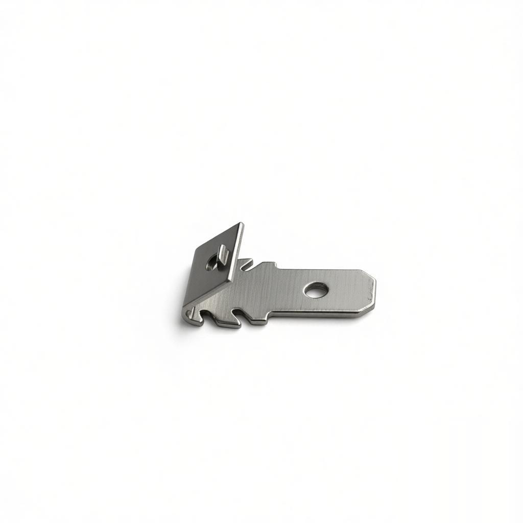
Springback Compensation in Metal Stamping: Design & Simulation Guide
Understanding Springback in Metal Stamping
Springback is the elastic recovery of a metal part after it has been deformed during stamping. This phenomenon occurs because the material tries to return to its original shape once the forming load is removed. Springback can lead to dimensional inaccuracies, affecting part quality and assembly. Understanding the mechanics of springback is crucial for developing effective compensation strategies.
Factors Influencing Springback
Several factors affect the magnitude of springback in metal stamping:
- Material Properties: Yield strength, elastic modulus, and work-hardening behavior significantly influence springback. High-strength steels exhibit greater springback than mild steels.
- Tool Geometry: The radius of bending, die clearance, and punch shape affect the stress distribution and thus springback.
- Process Parameters: Blank holder force, lubrication, and forming speed alter the stress state and springback.
- Thickness: Thinner materials spring back more relative to thicker ones due to lower bending stiffness.
By controlling these factors, engineers can minimize springback or design compensation features.
Design Strategies for Springback Compensation
Compensating for springback involves modifying the tool design to produce a part that springs back into the desired shape. Common strategies include:
- Overbending: Bending the part more than the required angle so that after springback, the final angle matches the specification. The amount of overbend is determined through simulation or trial.
- Adding Compensation Features: Incorporating local features like embosses, ribs, or beads that increase stiffness and reduce springback.
- Stress Relief Techniques: Using heat treatment or localized heating to reduce residual stresses.
- Adjusting Die Geometry: Modifying the die surface to account for springback, often by iteratively correcting the tool shape based on simulation results.
These strategies require careful analysis and often iterative redesign.
Simulation Techniques for Springback Prediction
Finite Element Analysis (FEA) is the most common simulation method for predicting springback. Key steps include:
- Material Modeling: Use accurate hardening models (e.g., isotropic, kinematic) that capture plastic behavior and unloading.
- Boundary Conditions: Define realistic friction, blank holder forces, and tool contacts.
- Element Selection: Shell or solid elements with appropriate integration points to capture bending stresses.
- Springback Analysis: After forming, release the tools and calculate the elastic recovery. The result shows the deviation from the desired shape.
Advanced simulation software (e.g., AutoForm, LS-DYNA, PAM-STAMP) allows for iterative compensation where the tool geometry is automatically adjusted until the part meets tolerances.
Below is a comparison of common simulation approaches:
| Method | Advantages | Disadvantages |
|---|---|---|
| Implicit (static) solver | Accurate for small deformations, fast for sheet metal | Can struggle with complex contact |
| Explicit solver | Handles large deformations and complex contacts well | Computationally intensive for springback step |
| One-step solver | Very fast, suitable for quick iterations | Less accurate for complex parts |
Practical Tips for Springback Compensation
- Start with Material Testing: Obtain accurate mechanical properties (stress-strain curve) for the specific batch of material. Use these in simulations for reliable predictions.
- Use Symmetry When Possible: Model only half or a quarter of the part to reduce simulation time, but be aware of asymmetric effects.
- Validate with Physical Trials: Always correlate simulation results with actual stamping. Adjust material models or friction parameters as needed.
- Iterate on Compensation: Use the springback results to modify the tool surface by the inverse of the deviation. Typically, two to three iterations yield convergence.
- Consider Process Stability: Even with compensation, variations in material thickness, lubrication, and press speed can cause residual springback. Design robust processes with tighter controls.
- Incorporate Robust Design: Use Design of Experiments (DOE) to identify process parameters that minimize sensitivity to springback.
Conclusion
Springback compensation is a critical aspect of high-precision metal stamping. By combining an understanding of material behavior, strategic tool design, and advanced simulation techniques, manufacturers can achieve tight tolerances and reduce trial-and-error. Implementing the strategies discussed above will not only improve part quality but also save time and cost in tool development. For optimal results, partner with experienced metal stamping services that utilize state-of-the-art simulation and compensation methods.
Frequently Asked Questions
What causes springback in metal stamping and how does it affect part quality?
Springback is the elastic recovery of a metal part after deformation during stamping, as the material tries to return to its original shape when the forming load is removed. This can lead to dimensional inaccuracies, affecting part quality and assembly. Understanding its mechanics is crucial for developing compensation strategies.
Which factors most significantly influence the amount of springback in stamped parts?
Key factors include material properties like yield strength and elastic modulus, with high-strength steels showing greater springback than mild steels. Tool geometry (bending radius, die clearance, punch shape), process parameters (blank holder force, lubrication, forming speed), and material thickness also matter—thinner materials spring back more due to lower bending stiffness.
What are the common design strategies to compensate for springback?
Common strategies include overbending (bending more than required so the final angle matches specs), adding local features like embosses or ribs to increase stiffness, using stress relief techniques like heat treatment, and adjusting die geometry iteratively based on simulation results. These require careful analysis and often iterative redesign.
How does Finite Element Analysis (FEA) help predict and correct springback?
FEA predicts springback by modeling material behavior with accurate hardening models, defining realistic boundary conditions, and using shell or solid elements to capture bending stresses. After forming, tools are released to calculate elastic recovery. Advanced software like AutoForm, LS-DYNA, or PAM-STAMP allows iterative tool geometry adjustment until the part meets tolerances.


