
BQUQ is a professional metal stamping manufacturer. Send us your drawings, and we will provide a quote within 12 hours.
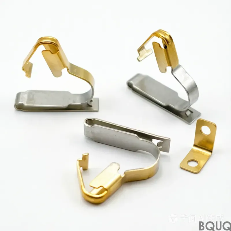
Multi-Physics Coupled Failure Mechanisms and Systematic Prevention Strategies in Stamping Processes
Introduction: Failure – An Unavoidable Technical Challenge in Stamping Production
As a high-volume metal forming process, the core competitiveness of metal stamping lies in the dual dimensions of efficiency and consistency. However, in high-speed, continuous, multi-station production scenarios, various failure issues emerge endlessly: die cracking, part fracture, wrinkling and stacking, excessive burrs, scrap floating, die jamming and part stacking... Each failure directly leads to production stoppage, die repair, and scrap, eroding profits and delivery credibility. According to statistics, stamping die costs typically account for 20% to 25% of the total part cost, while the original die manufacturing cost only accounts for about 40% of the total die cost, with post-repair and sharpening maintenance costs accounting for up to 60%. Therefore, a deep understanding of the multi-physics coupled failure mechanisms in the stamping process and the establishment of a systematic fault diagnosis and prevention system are core competencies that stamping engineering technicians must master.
This article provides an expert-level technical analysis from four dimensions: the mechanical mechanisms of stamping part quality defects, the types and root causes of die failures, the identification and handling of production faults, and preventive maintenance systems.
I. Stamping Part Quality Defects: Mechanical Mechanisms and Engineering Countermeasures
1.1 Cracking: The Inevitable Result of Strain Exceeding Limits
Mechanism Analysis: The essence of stamping part cracking is that the local strain of the material during forming exceeds its ultimate strain capacity (Forming Limit Curve, FLD). Cracking often occurs in processes such as drawing and flanging. Specific causes include: excessive local stress near the punch and die radii leading to tensile strength failure; fracture near the punch tip during bulging deformation; delayed cracking due to material hardening and embrittlement in complex forming areas under residual stress; and streak-like cracks caused by internal material impurities (usually parallel to the sheet rolling direction).
Engineering Countermeasures: The approach to solving cracking issues is divided into three levels. At the material level, use materials with better drawability, or apply local heating to difficult forming areas to improve elongation. At the process level, reasonably adjust draw bead parameters to control material flow speed, improve lubrication conditions, modify process addendum surfaces to optimize strain paths, or adjust blank holder force to make material flow more uniform. At the process sequence level, it is worth noting that CAE simulation studies based on Dynaform show that when optimizing process parameters cannot effectively avoid cracking, setting a piercing step before tensile fracture can significantly reduce the risk of cracking in subsequent steps – the stress redistribution after piercing disperses the strain originally concentrated in the critical section. This approach breaks through the traditional limitation of 'only parameter fine-tuning' and provides a solution dimension of process sequence reconstruction.
1.2 Wrinkling and Stacking: Manifestations of Unstable Compressive Stress
Mechanism Analysis: The root cause of wrinkling lies in the significant difference between the thickness direction and the planar direction dimensions of the sheet. When the compressive stress in the planar direction reaches a certain level, stability in the thickness direction is lost. Specific manifestations fall into two categories: material accumulation wrinkling, where too much material enters the die cavity and cannot be accommodated by the surface; and instability wrinkling, including flange instability due to insufficient blank holder force, uneven stress from non-uniform deep drawing, excessive part R angles causing overly fast material flow, unreasonable or undersized draw beads, and excessive clearance between the upper and lower dies.
Engineering Countermeasures: The core logic for solving wrinkling is to ensure material is held down and control material flow speed – too fast flow leads to wrinkling, too slow flow leads to cracking, and the optimal window must be sought in a tension balance. Measures include: checking model rationality during the product design phase to avoid saddle shapes; adding draw beads to absorb excess material; adjusting blank holder force and draw bead parameters; and switching to materials with better formability while meeting performance requirements. For already formed wrinkled parts, correction can be made in subsequent processes through restriking or flattening.
1.3 Springback: Elastic Recovery After Unloading
Mechanism Analysis: Springback is a dimensional deviation caused by the release of elastic internal stress after the stamping part is unloaded. The higher the yield strength of the material, the smaller the elastic modulus, and the more severe the work hardening, the greater the springback. For Advanced High-Strength Steel (AHSS) and Ultra-High-Strength Steel, springback has become the primary bottleneck limiting forming accuracy.
Engineering Countermeasures: Commonly used springback control methods in the industry include three types. Compensation Method: Based on experience or CAE simulation results, pre-set slopes or curved surfaces on the die that are equal in magnitude but opposite in direction to the springback, so that the formed part springs back to the target dimension after unloading. Stretch Bending Method: Apply tensile force during bending to change the internal stress distribution of the sheet metal and make it more uniform, thereby reducing springback. Overbending Method: Perform excessive bending to a smaller angle than the target, utilizing the material's springback characteristics to 'bounce back' to the target value. Additionally, setting bead lines on the punch or pre-punching notch-like grooves can also effectively suppress springback.
1.4 Burrs: The Most Intuitive Diagnostic Signal in Blanking
Mechanism Analysis: Burrs are the most common and easily overlooked quality signal in blanking. Their generation is directly related to the blanking clearance: the larger the clearance, the larger the burr, accompanied by shear warpage leading to decreased dimensional accuracy; if the clearance is too small, secondary shear surfaces and whisker-like burrs occur. Ideally, the shear surface in the blanking cross-section should account for 1/2 to 1/3 of the sheet thickness, and this state should be uniformly distributed. An increase in burrs is the first signal of wear on the punch and die cutting edges.
Engineering Countermeasures: When burrs exceed the allowable height, immediate die sharpening is required. If burrs are uneven, it indicates a shift in the blanking clearance, requiring clearance adjustment. For fine blanking processes, due to the use of V-ring indenter clamping and extremely small clearance (only 5‰~10‰ of material thickness), the shear surface finish can reach below Ra 0.2μm, making burrs almost invisible.
2. Mold Failure: From Damage Types to Systematic Diagnosis
2.1 Mold Damage: Combined Effects of Material, Heat Treatment, and Operating Conditions
Typical forms of mold damage include cracking, breakage, and expansion. The causes can be traced from three levels:
Design and Manufacturing Level: Mold material and heat treatment process are the primary factors. Excessive quenching temperature, unreasonable quenching method and time, improper selection of tempering times and temperature can all lead to early damage during service. Insufficient design of blanking hole size or depth can easily cause waste blockage and expansion cracking of the die. Improper spring force design or uneven height of equal-height spacers can cause the stripper plate to tilt or even overlap during punching, damaging parts.
Usage Level: Incorrect part installation direction, poor bolt tightening, excessively low working height adjustment, insufficient guide pillar lubrication, and feeder equipment failure can all cause mold damage.
Abnormal Operating Condition Level: If abnormal situations such as foreign objects entering the mold, overlapping parts, or waste blockage are not promptly addressed and production continues, it can easily lead to severe damage to the blanking plate, punch, lower die plate, and guide pillars.
2.2 Mold Sticking: Warning of Guide Failure and Unbalanced Force
Mold sticking manifests as inflexible or even jammed mold closing, requiring immediate shutdown for inspection; otherwise, the fault will escalate, potentially scrapping the entire mold. Main causes include: poor mold guidance or tilt; foreign objects between plates preventing close contact; insufficient mold strength design or uneven force distribution causing deformation; excessive mold installation positioning error or insufficient press precision causing interference; insufficient punch strength or excessively close positioning of large and small punches causing unbalanced lateral forces. The solution direction is to increase punch strength and enhance the guiding protection of the stripper plate.
2.3 Economic Decision-Making for Repair vs. Scrapping
When a mold is damaged, a choice between repair and scrapping must be made. Generally, damage to non-critical parts—such as breakage of a small punch, upsetting and shortening of a punch, cracking of a die plate, or chipping of a cutting edge—can be fully restored through repair. However, when critical parts are severely damaged, the one-time repair cost exceeds 70% of the original mold manufacturing cost, or the mold is near the end of its service life, the economic viability of repair is low, and scrapping and remanufacturing should be considered.
3. Production Failures: Easily Overlooked Systemic Issues
3.1 Scrap Floating: The 'Invisible Killer' of Regular Shapes
Scrap floating is a highly destructive failure in high-speed stamping. Scrap should fall into the discharge hole, but due to vacuum adhesion, oil film adhesion, or magnetic attraction, it sticks to the punch and moves upward, eventually falling onto the die surface. In the next stamping cycle, it is pressed into the workpiece, causing dents, damage, or even die breakage.
Engineering countermeasures: If scrap floating occurs frequently during the trial run, it indicates excessive clearance in the blanking die; the die should be remanufactured to reduce clearance. If it occurs sporadically, increase roughness in the die cavity using EDM to improve scrap detachment resistance. An overly smooth punch surface can exacerbate vacuum adhesion; adding air holes on the punch can eliminate negative pressure. In single-side blanking, add sharp corners on the non-blanking side to clamp the scrap. Additionally, using a 'kick-out pin' on the punch to physically push the scrap away, or vacuuming scrap from below, are mature solutions. Human factors such as insufficient demagnetization after sharpening or excessive stamping oil usage should also be noted.
3.2 Stacking and Discharge Hole Blockage: Easily Overlooked Major Risks
Stacking occurs when, after the final station cut-off, the produced part is not promptly blown out of the die, and the next stamping cycle overlaps and strikes it, easily damaging the die. Causes include insufficient blow air pressure, stamping oil adhesion, and parts hooking onto ejector pins. Countermeasures include: ensuring sufficient air pressure; adding ejector pins on both the die plate and stripper plate; designing a slope at the end of the die plate for parts to slide out; and ensuring the part to be cut extends at least half its length beyond the die plate to utilize gravity for self-release.
If a slug hole blockage is not detected in time, it can cause the punch to break or the die to crack. Ensure that the die backing plate's slug hole contour is larger than the die plate, and the lower die set is larger than the die backing plate, forming a progressively enlarged 'funnel' structure. Slug holes at small protruding areas should be appropriately enlarged to prevent scrap jamming.
3.3 Unstable Feeding: The Chronic Killer of Cycle Efficiency
Unstable feeding can affect cycle time at best and damage the mold at worst. Causes include feed pitch deviation, excessive spacing of lift pins causing strip sagging, insufficient strip lift height leading to hooking, small lift pin gaps increasing resistance, and overly wide or thin strips causing warping. Solutions include adjusting the pitch, adding more lift pins, increasing lift height, enlarging gaps, or adding a lift block in the middle of the strip.
IV. Preventive Maintenance System: Die Sharpening and Life Management
4.1 Precise Judgment of Sharpening Timing
Die edge wear is a gradual process, but many companies overlook the value of timely sharpening. Delaying sharpening causes the dulled edge to endure severe friction, leading to a vicious cycle of excessive wear. Ultimately, it requires several times the sharpening amount to restore sharpness, severely shortening the overall die life. The optimal sharpening time is when the burr height on the part is about to exceed the allowable limit—determine the wear level by checking burr height and distribution uniformity, part dimensions and geometric accuracy, and cut surface quality.
4.2 Control of Sharpening Amount
After multiple sharpenings, the die dimensions change. Especially for dies with a tapered die opening design (smaller at the top, larger at the bottom), sharpening the top surface inevitably increases the horizontal dimensions. Before sharpening, calculate based on the taper angle; during sharpening, measure the part dimensions to prevent dimensional deviation due to repeated sharpening.
Conclusion
The technical depth of stamping production often lies not in the forming principles themselves, but in the judgment and systematic problem-solving ability when facing various failures. Cracking requires a coordinated approach from three aspects: material, process, and operation sequence. Wrinkling must follow the core logic of 'holding the material and controlling the flow speed.' Burrs are the first signal of wear, requiring timely sharpening rather than letting the condition worsen. Abnormalities like scrap floating, double parts, and die jamming often stem from design-stage detail oversights. Truly efficient stamping workshops are those that have established a systematic fault database, accumulated a mapping of failure modes and countermeasures, and can feed experience back into the closed loop of die design and process optimization. In the era of smart manufacturing, these valuable failure data will become the 'fuel' for training AI fault diagnosis models, driving preventive maintenance from experience-driven to data-driven.
BQUQ is a professional metal stamping manufacturer. Please send us your drawings, and we will provide you with a quote within 12 hours.
Frequently Asked Questions
What percentage of total stamping part cost typically goes to die costs, and how is that split between original manufacturing and maintenance?
Stamping die costs typically account for 20% to 25% of the total part cost. The original die manufacturing cost only accounts for about 40% of the total die cost, while post-repair and sharpening maintenance costs account for up to 60%.
What are the main causes of cracking in stamping parts during drawing and flanging processes?
Cracking occurs when local strain exceeds the material's forming limit curve (FLD). Specific causes include excessive local stress near punch and die radii, fracture near the punch tip during bulging, delayed cracking from residual stress in complex areas, and streak-like cracks from internal material impurities parallel to the rolling direction.
What engineering countermeasures can be applied to solve stamping part cracking issues?
Solutions are divided into three levels: material level (use better drawability materials or local heating), process level (adjust draw bead parameters, improve lubrication, modify addendum surfaces, or adjust blank holder force), and process sequence level (CAE simulation with Dynaform shows setting a piercing step before tensile fracture can significantly reduce cracking risk).
How does CAE simulation help in preventing stamping part cracking?
CAE simulation studies based on Dynaform show that when optimizing process parameters cannot effectively avoid cracking, setting a piercing step before tensile fracture can significantly reduce the risk of cracking. This allows engineers to test and adjust process sequences virtually before physical production.


