
BQUQ is a professional CNC production expert. Please send us your drawings, and we will provide a quote within 12 hours.
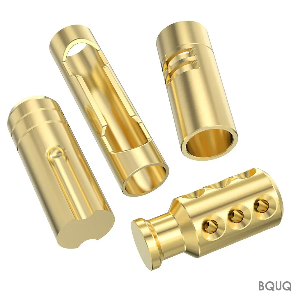
CNC Turn-Mill Composite Machining, Turn-Mill Machine Tools, One-Time Forming, B-Axis Turn-Mill Center, Multi-Process Integration, Complex Rotary Part Machining, Medical Device Precision Machining
Abstract
Turn-mill machining centers represent a paradigm shift in CNC machining from "process dispersion" to "process integration." Their core value lies in combining multiple processes such as turning, milling, drilling, tapping, and gear hobbing on a single machine tool with a single setup, fundamentally eliminating datum conversion errors caused by multiple setups in traditional multi-process manufacturing chains, while significantly reducing auxiliary time and work-in-process circulation cycles. Starting from the kinematic architecture of turn-mill machines, this article systematically analyzes the key supporting role of coordinated Y-axis, B-axis, and C-axis motions in the "one-shot" machining of complex rotational parts. It delves into the unique coordinate system switching strategies, tool vector planning, and synchronous motion control challenges in turn-mill CAM programming. Using aerospace high-temperature alloy shaft parts and medical titanium alloy orthopedic implants as typical cases, it provides production-verified process parameters and accuracy data. It further explores the unique advantages of turn-mill machining in "multi-variety, small-batch" flexible manufacturing scenarios, as well as the technical path for achieving closed-loop "machining-inspection-compensation" control through integrated in-process measurement. Finally, considering the gap between domestic turn-mill equipment and German/Japanese products, it analyzes breakthrough directions for core technology self-sufficiency.
I. Introduction: Why "Single Setup" Is the Key Proposition for Manufacturing Efficiency
In traditional manufacturing processes, a moderately complex rotational part—such as an aero-engine fuel nozzle housing or a surgical instrument handle for medical devices—often requires the following process chain: turning the outer diameter and face → transferring to a milling machine for slots and flats → transferring to a drilling machine for holes → transferring to a tapping machine for threads → transferring to a grinding machine for finishing critical mating surfaces. Each setup change is accompanied by: accumulation of datum positioning errors, consumption of work-in-process circulation time, redundancy in operator allocation across multiple machines, and quality fluctuation risks due to consistency differences among various machines.
Turn-mill machining centers are a systematic response to this production pain point. They integrate a turning spindle (typically with C-axis indexing), a milling spindle (configurable with B-axis swiveling), a tool magazine, and an automatic tool changer on a single machine, allowing all major machining processes from blank to finished part to be completed in a single setup. Their value lies not only in "saving processes" but also in "improving accuracy"—eliminating datum conversion errors, the most insidious quality killer in traditional manufacturing.
According to industry data, using turn-mill machining to replace traditional multi-process solutions can reduce the total machining cycle for complex shaft parts by over 50%, improve key dimension consistency by 1-2 IT grades, and reduce work-in-process inventory by over 60%-7. This generational leap in manufacturing efficiency is the fundamental driver behind the rapid penetration of turn-mill technology in high-value-added fields such as aerospace, medical devices, and precision hydraulics. According to market analysis, the global CNC machine tool market is expected to grow from $93.8 billion in 2025 to $134.3 billion in 2030, with high-end multi-axis equipment like turn-mill and five-axis machining being the core engine of this growth-6.
II. Kinematic Architecture: The Coordination Logic of Y-Axis, B-Axis, and C-Axis
The core difference between turn-mill machines and ordinary CNC lathes lies in their "multi-axis linkage" kinematic configuration.
C-Axis (Spindle Indexing): The turning spindle not only provides rotational main motion (for turning) but also offers precise indexing positioning and low-speed interpolation (C-axis mode). This allows the workpiece to be locked at any angle, providing a positioning reference for milling, drilling, and other processes. The indexing accuracy of the C-axis directly affects the positional accuracy of cross holes and slots.
Y-Axis: Traditional turning centers only move in the X-Z plane (radial-axial), so milling tools can only feed in the X direction (radial) or Z direction (axial), making it impossible to machine features offset from the center plane. The introduction of the Y-axis allows the milling spindle to move perpendicular to the X-Z plane, enabling functions such as milling flats, slots, and irregular contours on cylindrical surfaces, effectively "grafting" the machining capabilities of a vertical machining center onto a lathe.
B-axis (Milling Spindle Swivel): This is the 'core feature' of high-end mill-turn machines. The B-axis allows the milling spindle to swivel within a certain angle range (typically ±90 to ±120), enabling the tool to approach the workpiece surface at any angle for machining features such as angled holes, inclined surfaces, and complex 3D contours. When the B-axis is linked with the C-axis and X/Y/Z axes, the mill-turn machine essentially functions as a 5-axis machining center, capable of machining complex freeform surface parts like integral impellers and artificial joints.
This multi-axis configuration places extremely high kinematic computational demands on the CNC system of the mill-turn machine—it must handle the coordination of spindle speed and feed in turning operations, as well as the linked interpolation of multiple linear and rotary axes in milling operations, while rapidly switching coordinate system references between different operation modes.
III. CAM Programming and Process Strategy: Coordinate System Conversion and Tool Vector Management
CAM programming for mill-turn machining is significantly more challenging than for pure turning or pure milling, mainly reflected in the following aspects:
Dynamic Coordinate System Switching: Turning operations are typically programmed in the workpiece rotating coordinate system (cylindrical coordinate system), while milling operations define tool paths in the Cartesian coordinate system. Mill-turn CAM software (such as ESPRIT, GibbsCAM, NX CAM's mill-turn module) needs to automatically manage the conversion relationship between these two coordinate systems to ensure that milling tool paths are accurately executed under the rotation reference of the turning spindle.
Continuous Tool Vector Planning: When the B-axis is involved in motion, the orientation of the tool axis relative to the workpiece surface requires continuous planning. This is similar to the tool axis planning logic for 5-axis milling, but must consider the specific kinematic constraints of the mill-turn machine—such as the B-axis's swivel range and interference avoidance between the milling spindle and turning spindle. For machining rotary parts with multiple directional irregular features (such as hydraulic valve bodies and aviation connectors), the B-axis needs to frequently swivel between different angles, and the smoothness of path planning directly affects machining efficiency and surface quality.
Post-Processing Customization for Synchronous Motion: The post-processor for mill-turn machines is far more complex than that for ordinary 3-axis machines. It must correctly parse the CAM output of "toolpath data for milling operations in the turning coordinate system" and generate synchronized G-code that simultaneously drives C-axis indexing, B-axis tilting, and X/Y/Z feed. For high-end systems supporting RTCP (Rotational Tool Center Point), the post-processor only needs to output the tool tip point and tool axis direction, with the controller calculating each axis coordinate in real time; for systems without RTCP functionality, the post-processor must pre-calculate all axis coordinate values—this requires precise modeling of the machine's kinematic chain.
IV. Typical Applications of Mill-Turn in High-End Manufacturing
1. Aerospace: "One-Shot" Machining of Superalloy Shaft Parts
Taking a certain Inconel 718 high-pressure turbine shaft for an aircraft engine as an example, its geometric features include: variable-diameter outer diameter, stepped inner bore, end-face bolt holes, and circumferential oil grooves. The traditional process requires multiple steps such as rough turning, finish turning, transferring to a 5-axis machining center for groove milling, and then to a drilling machine for hole drilling.
Using a mill-turn machining center with B-axis and Y-axis, the process flow is simplified to: one-time clamping → rough and finish turning of outer diameter → inner bore turning → C-axis indexing → end-face groove milling → B-axis tilting → drilling of angled oil holes → tapping → in-process measurement → finished part unloading. Key dimensional accuracy is consistently maintained at IT6 grade, coaxiality error is reduced from 0.025mm in the traditional process to 0.008mm, and total machining time is reduced from 220 minutes to 105 minutes.
2. Medical Orthopedic Implants: Precision Manufacturing of Titanium Alloy Joint Stems
The artificial hip joint stem is a typical complex rotational part, made of Ti6Al4V, with a surface finish requirement of Ra0.4μm or below and extremely high taper fit precision. Mill-turn machining can complete the following on a single machine: turning the outer contour → milling the proximal irregular plane → C-axis indexing → drilling locking holes → B-axis tilting → milling the tapered stem → in-process laser measurement of critical dimensions → compensation and correction → completion. The one-time clamping strategy completely eliminates the impact of multiple clamping on the taper fit precision of the stem, increasing the product yield rate from 87% in the traditional process to 98%, and reducing the single-part machining cycle from 75 minutes to 42 minutes.
3. Precision Hydraulics: Machining Challenges of Cross Holes in Valve Sleeves
The inner wall of a hydraulic servo valve sleeve features multiple cross holes and annular grooves. The angular and positional accuracy between holes directly determines the flow control characteristics of the valve. A mill-turn machine tool with precision C-axis indexing and B-axis tilting can complete all internal hole features in a single clamping, avoiding the cumulative circumferential positional errors caused by the traditional process of "turning the inner bore first, then transferring to a machining center for indexing and drilling". Practical data shows that the circumferential positional accuracy of cross holes can be controlled within ±0.02, meeting the highest grade requirements for aerospace hydraulic systems.
V. Technical Trends and Localization Challenges of Mill-Turn Technology
Current mill-turn machining centers are evolving in two directions: first, deep integration with online measurement systems to achieve a real-time closed loop of "machining-inspection-compensation", ensuring key dimensions meet design tolerances without secondary clamping measurement; second, incorporating digital twin technology to perform collision detection and process verification on virtual machines before actual machining, significantly reducing the trial-cutting risks of complex mill-turn programs.
However, there is still a gap between domestic mill-turn equipment and international advanced levels. According to industry analysis, Japanese manufacturers maintain a high market share in China for high-end machining centers and mill-turn machines, while the localization level of core components such as CNC systems, ball screws, and guide rails remains low. Fanuc, Mitsubishi, and Siemens still hold a major share in high-end CNC system sales, which limits the competitiveness of domestic mill-turn machines in terms of accuracy retention and multi-axis machining efficiency.
Breakthroughs in domestic mill-turn machine tools depend on independent control of CNC systems—such as the continuous iteration of five-axis linkage control algorithms by Huazhong CNC—and on a deep understanding of the coupling between "process, machine tool, and tooling". Mill-turn machining is not simply a "lathe with a milling head" but requires machine tool designers to adopt a forward design approach based on the process chain of typical parts. This cognitive shift is key to advancing domestic mill-turn equipment from "usable" to "easy to use".
BQUQ is a professional CNC production expert. Please send us your drawings, and we will provide a quotation within 12 hours.
Frequently Asked Questions
What is the main advantage of using a turn-mill machining center compared to traditional multi-process manufacturing?
The main advantage is completing turning, milling, drilling, tapping, and gear hobbing in a single setup. This eliminates datum conversion errors caused by multiple setups, reduces auxiliary time and work-in-process circulation cycles, and improves accuracy by avoiding quality fluctuations from using different machines.
How does a turn-mill machine handle complex rotational parts like aerospace or medical components?
It uses coordinated Y-axis, B-axis, and C-axis motions to enable 'one-shot' machining. For example, aerospace high-temperature alloy shaft parts and medical titanium alloy orthopedic implants are machined with production-verified process parameters and accuracy data, ensuring precision without multiple transfers between machines.
What are the key challenges in CAM programming for turn-mill machining?
Challenges include coordinate system switching strategies, tool vector planning, and synchronous motion control. These are critical for managing the integrated processes and ensuring accurate machining of complex parts, as highlighted in the article's analysis of turn-mill CAM programming.
Can turn-mill machining support flexible manufacturing for small batches?
Yes, it offers unique advantages in 'multi-variety, small-batch' scenarios. By integrating processes and enabling closed-loop 'machining-inspection-compensation' control through in-process measurement, it reduces setup changes and improves efficiency, making it ideal for flexible production needs.


