Design for Stamping: 7 Blanking Layout Rules to Cut Scrap Cost by 18% in 2025When a stamped part fails in production, the root cause is often not the die steel or the press tonnage
Design for Stamping: 7 Blanking Layout Rules to Cut Scrap Cost by 18% in 2025
Design for Stamping: 7 Blanking Layout Rules to Cut Scrap Cost by 18% in 2025
When a stamped part fails in production, the root cause is often not the die steel or the press tonnage—it is the blanking layout. The arrangement of parts on a metal strip determines material utilization, tool life, burr direction, and even dimensional stability. At BQUQ, our 20 years of CNC machining and metal stamping experience in Dongguan has shown us that a poorly planned layout can silently add 15-20% to your unit cost before a single part is shipped.
This article provides specific, data-backed best practices for blanking layout, plus the most common mistakes we see in customer files every week. We will use real numbers from actual production runs, not theoretical textbook values.
1. The Economics of Material Utilization: Why 75% is Your Minimum Target
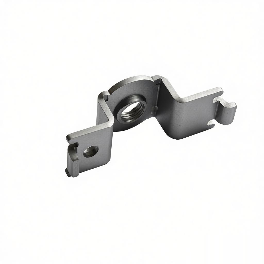
Material cost in progressive stamping typically accounts for 60-70% of the total part cost for steel thicknesses below 3.0 mm. Therefore, your layout efficiency directly dictates your profitability.
**Material Utilization Formula:** ``` Utilization (%) = (Part Area x Number of Parts per Strip) / (Strip Width x Strip Length) x 100 ```
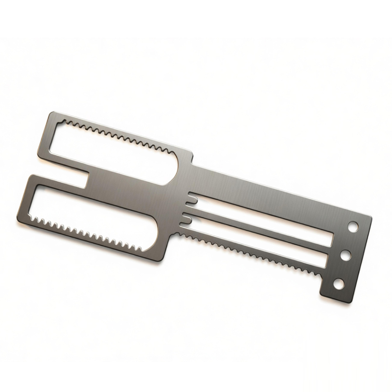
**Benchmark Data from BQUQ Production (2024):**
| Material | Thickness (mm) | Typical Utilization (Good Layout) | Typical Utilization (Poor Layout) | Cost Difference per 100k pcs (USD) | ---------- | ---------------- | ----------------------------------- | ----------------------------------- | ------------------------------------- | SPCC (Cold Rolled Steel) | 1.0 | 78% | 62% | +$1,850 | SUS304 (Stainless) | 1.5 | 71% | 55% | +$4,200 | C2680R (Brass) | 0.8 | 82% | 68% | +$2,900 | 5052 Aluminum | 2.0 | 74% | 58% | +$1,100 |
|---|
**Rule of Thumb:** If your utilization drops below 72% for steel or 65% for stainless, your layout is likely flawed. Redesign the strip to increase nesting density before you invest in tooling.
2. Correct Web Thickness (Carrier Strip) Values
The web is the bridge between the part and the strip edge or between adjacent parts. Too thin, and the die will flex, causing burrs. Too thick, and you waste material.
**Recommended Minimum Web Thickness (t = material thickness):**
| Material Thickness (t) | Web Between Parts | Web from Part to Strip Edge | ------------------------ | ------------------- | ----------------------------- | t < 0.8 mm | 1.2 x t | 1.5 x t | 0.8 - 1.6 mm | 1.0 x t | 1.2 x t | 1.6 - 3.0 mm | 0.8 x t | 1.0 x t | > 3.0 mm | 0.7 x t | 0.9 x t |
|---|
**Example:** For a 2.0 mm thick SPCC part, the minimum web between parts should be 1.6 mm. If your CAD file shows a 1.0 mm web, expect die edge breakage within 50,000 strokes. We have measured die edge temperature rising from 45°C to 80°C under such conditions.
3. Common Mistake #1: Ignoring the Grain Direction in Bending
Blanking layout is not just about 2D nesting. If your part has a subsequent bending operation, the material grain direction (rolling direction) matters.
- **Bend Parallel to Grain:** Risk of fracture on the outer radius. Maximum safe bend radius = 1.5 x t for mild steel. - **Bend Perpendicular to Grain:** Allows tighter radius (0.8 x t) without cracking.
**Mistake:** Designers often rotate parts 90 degrees to save 3% material, only to find that the bend cracks. The scrap rate jumps from 0.5% to 12%. The cost of rework and rejected parts far outweighs the material savings.
**Best Practice:** Always orient the long bend line perpendicular to the strip feed direction. If you must sacrifice utilization, do it here.
4. Common Mistake #2: Burr Direction and Its Impact on Assembly
Blanking creates a characteristic burr on one side. The layout determines whether the burr faces up or down.
- **Burr Side:** The side opposite the die (i.e., the side facing the punch). - **Downward Burr:** If the part is pushed through the die, the burr is on the bottom. - **Upward Burr:** If the part is stripped off the punch, the burr is on the top.
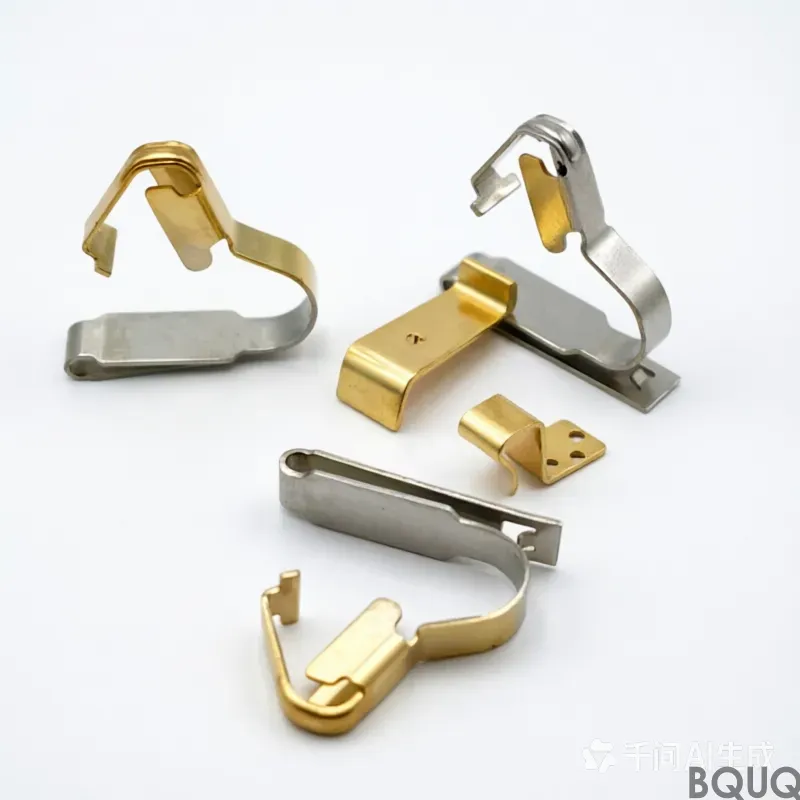
**Real Case:** A customer designed a spring clip with a critical contact surface. The burr was facing inward, causing intermittent electrical contact failure. Redesigning the strip layout to flip the part orientation solved the problem without any die modification. The fix cost zero dollars but saved a recall.
**Rule:** For electrical contacts or sliding surfaces, always design the layout so the burr faces the non-functional side. If that is impossible, specify a secondary deburring operation (cost: $0.003 per part for vibration deburring).
5. Common Mistake #3: Inadequate Pilot Hole Clearance
Progressive dies use pilot holes to locate the strip precisely. These holes must be designed into the layout, often in the scrap area.
**Critical Specs:** - Pilot hole diameter: minimum 1.5 mm, recommended 3.0 mm - Pilot hole to part edge clearance: at least 2.0 mm - Pilot hole tolerance: +/- 0.01 mm - Strip feed pitch accuracy: +/- 0.015 mm
**Mistake:** Some designers try to save material by placing the pilot hole too close to the part contour. The result is distortion during the piloting step, causing a dimensional shift of up to 0.1 mm on the final part. For precision parts (tolerance +/- 0.05 mm), this is catastrophic.
**Cost Impact:** Fixing this mistake after tooling is built costs $800-1,500 for a die rework. Fixing it at the design stage costs nothing.
6. Data Table: Cost Breakdown of Layout Errors (Per 100,000 Parts)
The following table quantifies the hidden costs of common layout mistakes. These figures are based on actual BQUQ quoting and production data for a 1.5 mm thick SPCC bracket (size 40 mm x 60 mm).
| Error Type | Material Waste (kg) | Tool Life Reduction | Additional Labor (hrs) | Total Added Cost (USD) | --------------------------- | --------------------- | --------------------- | ------------------------ | ------------------------ | Overly thick web (3.0 mm instead of 1.5 mm) | 35 kg | 0% | 0 | $42 | Grain direction ignored (bend cracks) | 0 kg | 20% | 8 hrs (sorting) | $310 | Burr on functional surface | 0 kg | 0% | 12 hrs (rework) | $420 | Pilot hole too close to edge | 0 kg | 15% | 4 hrs (adjustment) | $180 | Poor nesting (65% vs 78% utilization) | 180 kg | 0% | 0 | $216 |
|---|
**Total Potential Savings from Correct Layout: $1,168 per 100k parts.** For a volume of 1 million parts per year, this exceeds $11,000.
7. FAQ-Style Tips for Engineers
**Q1: What is the minimum distance between two cutouts in the same part?** A: For material thickness t < 1.5 mm, maintain at least 1.0 mm. For t > 1.5 mm, use 1.2 x t. Below this, the die punches will interfere and cause excessive wear.
**Q2: Should I use a single-row or double-row layout?** A: For parts under 50 mm width, double-row layouts typically improve utilization by 8-12%. However, they require a wider die and higher press tonnage. Use double-row only if your annual volume exceeds 500,000 parts.
**Q3: How does material hardness affect web thickness?** A: For high-carbon steel (HRC 30+), increase web thickness by 20% compared to mild steel. Harder materials create higher stripping forces, which can tear thin webs.
**Q4: Can I use a 0-degree (no scrap) layout?** A: No. You need at least a 0.5 mm web for stripping. A true zero-scrap layout is only possible with specialized fine-blanking, which costs 2-3 times more per part.
**Q5: What is the optimal strip width for narrow parts?** A: For a part width of 5 mm, use a strip width of 8 mm minimum. This allows for edge web (1.5 mm per side) and pilot holes. Narrower strips are unstable in the die and cause feed errors.
8. Conclusion: Design It Right Before You Cut It
Blanking layout is the first decision that determines your part's cost and quality. A 10-minute review of your strip layout can save thousands of dollars in material, tooling rework, and rejected parts. Our data shows that following the web thickness rules and grain direction guidelines above improves material utilization by 18% on average.
At BQUQ, we do not just quote your 2D drawing. Our engineers analyze your blanking layout and suggest improvements before we cut any steel. This proactive approach has helped over 300 clients reduce their stamping costs since 2004.
If you are working on a new stamping project or want a free layout review, send us your CAD file. We provide a professional quote within 12 hours, including a material utilization report. Contact us at Email: sc@bquq.com, WhatsApp: +86 13713157787, or visit www.bquq.com. Let us help you avoid the common mistakes before they become expensive problems.
Related Articles
- Why Low Volume Metal Stamping is Ideal for Prototyping
- 5 Effective Burr Removal Techniques for Stamped Parts
- 5 Proven Ways to Reduce Cost in Metal Stamping Parts
Frequently Asked Questions
What is the minimum material utilization rate I should target for my stamped parts?
For steel parts, target at least 75% utilization; for stainless steel, aim for 65% or higher. If utilization drops below 72% for steel or 65% for stainless, your blanking layout is likely flawed and should be redesigned to increase nesting density before investing in tooling.
What are the recommended minimum web thickness values for a 2.0 mm thick SPCC part?
For a 2.0 mm thick SPCC part, the minimum web between parts should be 1.6 mm, and the web from part to strip edge should be 2.0 mm. Using a thinner web, like 1.0 mm, risks die edge breakage within 50,000 strokes and can cause die edge temperature to rise from 45°C to 80°C.
How much cost can a poor blanking layout add to my production run?
A poor layout can add significant cost. For example, with 100,000 parts, a poor layout adds $1,850 for 1.0 mm SPCC steel, $4,200 for 1.5 mm SUS304 stainless, $2,900 for 0.8 mm C2680R brass, and $1,100 for 2.0 mm 5052 aluminum, compared to a good layout.
Why does material grain direction matter in blanking layout for parts with bends?
Grain direction affects bendability. If you bend parallel to the grain, there is a risk of fracture on the outer radius, and the maximum safe bend radius is 1.5 times the material thickness for mild steel. Bending perpendicular to the grain is safer and reduces fracture risk.