
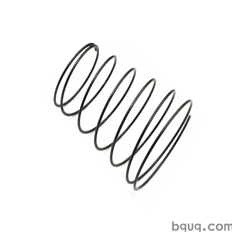
Assembly Tooling for Springs: Jigs and Handling
Short answer: Spring assembly tooling exists to control three failure modes — coil distortion, tang or hook damage, and spring loss during insertion. A workable jig typically holds the spring on a pilot rod 0.1–0.2 mm smaller than the spring's minimum inner diameter, limits compression to the design solid height plus 5–10%, and captures the part so it cannot eject. For most 0.3–2.0 mm wire springs, that means a hardened pilot, a lead-in chamfer of 15–20°, and a shallow counterbore. BQUQ builds springs to ±0.005 mm on CNC-machined features and quotes custom spring and tooling work in 12 working hours, so jig dimensions can be matched to the actual spring batch rather than the nominal drawing.
Why Spring Assembly Tooling Decides Whether a Good Spring Works
A spring that measures perfectly in the inspection room can still fail on the line. The reason is almost always handling, not manufacturing. A compression spring that is compressed past solid, a torsion spring whose leg is bent past its elastic limit, or an extension spring whose hook is opened by a screwdriver all leave the factory as good parts and arrive at the assembly station as scrap.
The economics are straightforward. A 0.5 mm wire compression spring might cost a few cents. The subassembly it sits in might cost several dollars, and the downtime to clear a jammed spring can cost far more than the spring itself. Tooling is cheap insurance, and it is usually the cheapest part of the whole project.
There is also a quality-system argument. If assembly is done by hand with pliers and improvisation, spring performance varies with operator technique. If assembly is done with a fixed jig, the spring sees the same loads every cycle. That repeatability is what makes downstream testing meaningful — and it is what an ISO9001 process is designed to deliver.
What Are the Three Failure Modes to Design Against?
Almost every spring assembly problem falls into one of three categories. Designing tooling means addressing each one explicitly.
Coil distortion and over-compression
Compressing a spring beyond its solid height forces coils into each other. On light wire this bows the coils outward or twists the end coils out of square. Even if the spring survives, its free length and rate shift, and the load at installed height drifts outside tolerance.
The fix is a hard stop. The jig should physically prevent travel past the design solid height plus a small margin — typically 5–10% for static applications, and effectively zero margin for springs that are already close to solid at working height. If your spring runs near solid height in service, review the spring solid height guide before you finalize the jig travel.
Tang, leg, and hook damage
Torsion springs and extension springs fail at their ends far more often than in the coils. A torsion leg bent past its yield point will not return to the designed angle. An extension hook opened with a screwdriver loses its loop diameter and can pull straight under load.
Tooling for these parts should locate on the leg or hook with a form-fitting pocket rather than a flat blade, and should rotate or translate the spring into position instead of prying it. Where the leg must be deflected during installation, keep the deflection within the elastic range and, if possible, install the spring in the unloaded position and preload it afterward.
Ejection, loss, and contamination
Small springs launch. A compression spring released under preload can travel several meters, and a spring that lands in a machine cavity becomes a foreign object risk. Loose springs also tangle in bulk bins, which damages plating and creates handling scrap.
Retention is the answer: a light capture feature, a magnetic or vacuum pickup, or a shroud that keeps the spring on the pilot until the mating part is in place. For high-volume lines, feeding springs in oriented tubes or tape rather than loose bins eliminates most of this class of problem.
How Do You Size a Pilot Rod or Mandrel?
The pilot is the single most important dimension in most spring assembly jigs. It must be small enough to slide into the spring without scraping the bore, and large enough to keep the spring concentric and square during compression.
A practical starting point is 0.1–0.2 mm smaller than the spring's minimum inner diameter. For tighter assemblies, or for springs with a large length-to-diameter ratio, go closer to 0.1 mm and add a generous lead-in chamfer. For springs that will be plated or coated after coiling, remember that the coating reduces the inner diameter — sometimes by 0.01–0.03 mm per side — so the pilot must be sized against the finished part, not the bare wire form.
| Spring type | Pilot / mandrel sizing | Lead-in | Typical retention method |
|---|---|---|---|
| Compression, free length < 4× OD | 0.10–0.15 mm under min ID | 15° chamfer | Shallow counterbore shoulder |
| Compression, free length > 4× OD | 0.10 mm under min ID, add mid-support | 20° chamfer | Counterbore plus guide bushing |
| Torsion, leg located in pocket | Body pilot 0.15 mm under min ID | 20° chamfer | Form-fitting leg pocket |
| Extension, hook over post | Post 0.05–0.10 mm under hook ID | Rounded post top | Retaining clip or shoulder |
| Wave or disc stack | Bore 0.10–0.20 mm over max OD | 15° chamfer | Sleeve with end stop |
Where the spring is compressed and released repeatedly in a test fixture, harden the pilot to at least 50 HRC and polish it. A soft, galled pilot will scratch the inside of the spring and, on stainless or plated parts, that scratch becomes a corrosion initiation site.
What Does a Workable Compression Spring Jig Look Like?
A compression spring jig is usually three features: a pilot, a stop, and a shoulder.
The pilot keeps the spring straight. The stop limits travel so the spring cannot be crushed past solid. The shoulder — usually a counterbore or a step — squares the spring's end coil against the mating face so the spring seats flat rather than cocked.
For hand assembly, a simple arbor press with a guided plunger and an adjustable stop covers most needs. For powered assembly, the same geometry is built into the press tooling, with the addition of a sensor or mechanical interlock that prevents a double-feed or a missing spring from being pressed.
Two details are worth calling out. First, the counterbore depth should be slightly less than the spring's wire diameter so the end coil is captured but not pinched. Second, if the spring has closed and ground ends, the ground face should sit against a flat, hardened surface; if it has open ends, a shallow locating groove helps prevent the end from walking.
How Should Handling Change for Torsion and Extension Springs?
Torsion and extension springs need different thinking because their function lives in the ends.
For torsion springs, the assembly tooling should control the angular position of both legs simultaneously. A two-pocket fixture that holds the body and both legs lets the operator place the spring without bending anything. If the spring must be wound during installation, the fixture should rotate the leg about the spring axis — never bend it sideways — and the rotation should stop at the working angle rather than continuing to a hard stop.
For extension springs, the hook is the weak point. Posts and anchors should have a radius at least as large as the hook's inner radius, and the hook should be captured so it cannot open under load. Where an extension spring is stretched during installation, keep the stretch within the initial tension plus a modest margin, and avoid repeated re-stretching of the same part during rework.
| Handling risk | Compression | Torsion | Extension |
|---|---|---|---|
| Primary damage mode | Coil bow, over-compression | Leg bend, body twist | Hook opening, loop yield |
| Key jig feature | Pilot and hard stop | Body pilot plus leg pockets | Rounded post and hook capture |
| Common mistake | Pressing past solid height | Prying the leg with a blade | Stretching to install |
| Inspection after assembly | Free length, squareness | Leg angle, torque at angle | Length at load, hook geometry |
How Do You Match Tooling to Spring Wire Diameter and Batch?
Tooling tolerances should scale with the spring, not be fixed. A 0.3 mm wire spring needs a pilot held to a few hundredths of a millimeter; a 3 mm wire spring is far more forgiving.
The practical rule is that the pilot clearance should be roughly 20–40% of the wire diameter, capped at about 0.2 mm. Below that, the spring will not slide on cleanly. Above it, the spring can tilt and the end coil can catch.
Batch consistency matters just as much. If the inner diameter varies from lot to lot — which happens with changes in wire diameter, coiling setup, or heat treatment — a single fixed pilot may work for one lot and jam the next. This is one reason to control the spring wire diameter specification tightly and to keep tooling drawings tied to the finished spring drawing rather than to a nominal value.
For low-volume or prototype builds, an adjustable pilot with interchangeable sleeves is usually more economical than a set of dedicated fixtures. If you are still deciding how many parts to order, the trade-offs are covered in the MOQ explainer.
What Should Be Inspected After Assembly?
Assembly inspection should be fast, objective, and tied to the spring's function.
At minimum, check free length or installed length, squareness of the end coils, and the presence and orientation of legs or hooks. For critical applications, add a load check at the installed height or a torque check at the working angle. These are the same characteristics that matter in the spring's own inspection plan, so the fixtures and gauges can often be shared.
Two process controls are also worth building in. First, a poka-yoke that prevents assembly with no spring or with two springs. Second, a defined rework rule: if a spring has been compressed past solid or a leg has been bent past yield, it is scrap, not rework. Sorting good springs from damaged ones by eye is not reliable.
Frequently Asked Questions
Q: How much clearance should a spring assembly pilot have?
A: A practical starting point is 0.10–0.20 mm under the spring's minimum inner diameter, which is roughly 20–40% of the wire diameter for common sizes. Tight assemblies and long springs favor the smaller end of that range with a 15–20° lead-in chamfer. Always size the pilot against the finished spring, including any plating or coating thickness, not the bare coiled part.
Q: Can I assemble springs by hand without a jig?
A: For very small quantities and low-risk parts, yes — but hand assembly is where most spring damage happens. Pliers open hooks, blades bend torsion legs, and uncontrolled compression crushes coils past solid height. Even a simple pilot rod and a hard stop removes most of that risk at negligible cost. If the spring is safety-related or the subassembly is expensive, tooling is not optional.
Q: What is the biggest cause of spring failure during assembly?
A: Over-compression of compression springs and leg or hook deformation on torsion and extension springs. Both come from the same root cause: the assembly method allows travel or deflection beyond the spring's elastic or geometric limit. A mechanical hard stop and a form-fitting pocket for the ends address nearly all of it. Damage is usually invisible on the outside of the spring, so it is often only found at final test.
Q: How do I prevent small springs from being lost or ejected?
A: Retain the spring on the pilot or in a capture feature until the mating component is in place, and feed springs in oriented tubes or tape rather than loose bins. For very small parts, a light vacuum or magnetic pickup helps. Loose springs in a machine cavity are both a loss problem and a foreign object risk, and the cost of a simple shroud is almost always lower than the cost of a recall.
Q: Does BQUQ supply assembly tooling along with springs?
A: BQUQ manufactures springs and precision-machined components in one ISO9001 factory in Dongguan, with CNC machining held to ±0.005 mm. That means pilot rods, stops, and fixture plates can be produced to match the actual spring batch rather than a nominal drawing. Quotes, including tooling, are returned in 12 working hours, and MOQ is flexible for prototype and short-run builds.
Related Resources
- About BQUQ — ISO9001 factory in Dongguan with four production lines under one roof.
- Compression springs — coil, wire diameter, and end configuration options.
- Torsion springs — leg forms, angles, and torque specifications.
- Extension springs — hook styles, initial tension, and length at load.
- Technical articles — spring design, materials, and manufacturing guides.
- Industry trends — sourcing and supply chain notes for OEM buyers.
- Contact — send drawings for a 12-hour quote.
Authored by the BQUQ Engineering Team. BQUQ (Dongguan) runs CNC machining (±0.005 mm), metal stamping, custom springs, and heat sink production in one ISO9001 factory. Source-direct from Dongguan, China — quote in 12 hours: sc@bquq.com | WhatsApp +86 13713157787 | www.bquq.com


