
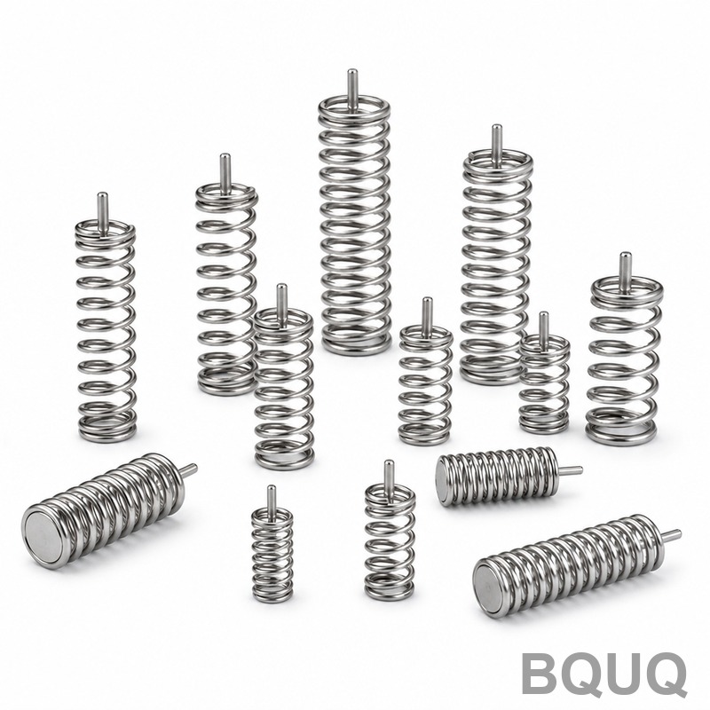
Plating and Powder Coating Springs: Effects on Rate
Short answer: Plating and powder coating do change spring rate, but only slightly — typically 1-4% for standard electroplated or electroless coatings, and 5-15% for thick powder coats on small wire. The mechanism is simple: coating adds mass to the wire and, more importantly, changes the wire diameter and the friction between adjacent coils. Rate scales with the fourth power of wire diameter, so a 0.05 mm coating layer on a 1.0 mm wire is a 10% diameter increase and roughly a 20% rate increase before friction effects. Powder coating adds 60-120 µm per side, which is significant on thin wire and negligible on heavy wire. The real risk is not rate shift — it is coil bind, hydrogen embrittlement and fatigue life.
Why Coatings Are Applied to Springs in the First Place
Springs are coated for three reasons, and the coating choice almost always follows from which reason dominates.
Corrosion protection. Carbon steel springs — the overwhelming majority of compression, extension and torsion springs made from music wire, oil-tempered wire or chrome-silicon — will rust in humid or mildly acidic environments. Zinc plating, zinc-nickel plating, electroless nickel and powder coating all interrupt the corrosion cell.
Wear and friction control. In a spring that slides against a bore, a plunger or another spring, surface hardness and lubricity matter. Electroless nickel-phosphorus and hard chrome reduce wear and keep the rate stable over millions of cycles.
Appearance and electrical insulation. Visible springs on consumer hardware are often powder coated for colour matching. Springs used near electrical contacts may be coated to provide dielectric separation.
Each of these goals pushes toward a different coating thickness, and thickness is exactly what drives the rate change.
How Coating Thickness Changes Spring Rate
The compression spring rate formula is:
k = G·d⁴ / (8·D³·n)
Where G is the shear modulus, d is wire diameter, D is mean coil diameter, and n is the number of active coils.
The key insight: rate depends on the fourth power of wire diameter. A coating that increases d by 2% increases rate by roughly 8%. A coating that increases d by 5% increases rate by roughly 22%.
But coatings do not behave like solid wire. They sit on the surface, they are softer than steel, and they shear slightly under load. The practical outcome is a rate increase that is smaller than the theoretical d⁴ prediction, because the coating contributes much less shear stiffness than the base wire.
| Coating | Typical thickness per side | Effect on wire diameter (1.0 mm wire) | Indicative rate increase |
|---|---|---|---|
| Zinc electroplate | 8-15 µm | +1.6% to +3.0% | 1-3% |
| Zinc-nickel electroplate | 8-12 µm | +1.6% to +2.4% | 1-2.5% |
| Electroless nickel | 10-25 µm | +2.0% to +5.0% | 2-5% |
| Phosphate + oil | 2-5 µm | +0.4% to +1.0% | <1% |
| Powder coat | 60-120 µm | +12% to +24% | 8-15% (see notes) |
| PTFE / dry film | 10-20 µm | +2.0% to +4.0% | 1-3% |
Figures are typical and indicative. Actual results depend on wire diameter, coating process control and spring geometry.
Note the powder coat row. On a 1.0 mm wire, a 100 µm powder coat is a 20% diameter increase, which theoretically implies a rate increase above 80%. In practice the measured increase is far lower — usually 8-15% — because powder coat is a polymer with a shear modulus roughly two orders of magnitude below steel, and because the coating on the inner face of the coil compresses rather than carrying shear. On wire above 3 mm the effect drops below 3% and is usually lost in normal rate tolerance.
The Coil Bind Problem Is Bigger Than the Rate Problem
Coating thickness consumes clearance between coils. If a compression spring is designed to solid height with only 0.2 mm of clearance per gap, a 100 µm powder coat on both adjacent wire surfaces adds 0.2 mm to the gap — and the spring now binds before reaching its designed solid height.
For powder coated springs, always specify the coated solid height, not the bare wire solid height. A safe rule is to add 2.2 times the coating thickness per side to the solid height calculation, then verify.
Plating Processes and Their Specific Effects
Electroplating (Zinc, Zinc-Nickel, Nickel, Chrome)
Electroplating is an immersion process. Hydrogen is generated at the cathode surface, which means hydrogen embrittlement is a real risk for high-strength steel springs — typically those above 1,400 MPa tensile strength, which includes most music wire and chrome-silicon springs.
The standard mitigation is a post-plate bake: 190-220 °C for 4-24 hours, started within one hour of plating. This is a process control requirement, not an optional step. If your supplier cannot describe their bake schedule, the coating is a fatigue risk regardless of what it does to rate.
Electroplating also builds unevenly. Current density is higher on outer coil faces and at coil ends, so thickness varies across the part. On a tightly wound spring, the inner faces of coils may receive 40-60% of the nominal thickness. Rate effect is therefore non-uniform, and so is corrosion protection.
Electroless Nickel
Electroless nickel deposits evenly regardless of geometry, which makes it the preferred coating for tightly wound springs and for parts with complex ends. Thickness control is good — ±10% is achievable. The trade-off is cost and bath chemistry management; electroless nickel is typically 2-4 times the cost of zinc plating.
Because deposition is uniform, the rate increase is more predictable than with electroplating. If your application needs a coating and a tight rate window, electroless nickel is usually the better engineering choice.
Mechanical Plating and Zinc Flake Coatings
Mechanical plating (peen plating) and zinc flake systems such as Geomet or Dacromet avoid hydrogen embrittlement entirely because there is no electrolytic hydrogen generation. They are the standard choice for high-strength springs in automotive and heavy equipment. Thickness is typically 8-20 µm, so rate effect stays in the 1-3% band.
The trade-off: these coatings are less decorative and typically only available in grey or silver.
Powder Coating Springs: What Actually Happens
Powder coating is applied electrostatically and cured at 180-200 °C. For springs, this creates three distinct issues.
Thickness is large and variable. A nominal 80 µm coat on a coil spring may range from 50 µm on inner faces to 150 µm on outer faces and coil ends. On small wire this variability alone can push rate outside a tight tolerance band.
Cure temperature can relax the spring. Springs are stress-relieved at temperatures close to the powder cure temperature. A 200 °C cure for 15-20 minutes on a spring that was stress-relieved at 200 °C is usually safe, but a spring that was only stress-relieved at 180 °C may lose load. The result is a lower spring rate after coating — the opposite of the thickness effect. These two effects partially cancel, which is why powder coated springs often measure closer to nominal than theory predicts.
Flexing cracks the coating. Powder coat is brittle relative to steel. On a spring that deflects significantly, the coating on the outer fibre of the wire will craze and eventually flake. This is acceptable for cosmetic springs but not for corrosion-critical ones. If the spring must flex and resist corrosion, use a ductile coating — zinc flake, electroless nickel, or a phosphate plus oil system.
| Consideration | Electroplated zinc | Electroless nickel | Powder coat |
|---|---|---|---|
| Typical thickness | 8-15 µm | 10-25 µm | 60-120 µm |
| Rate shift (indicative) | 1-3% | 2-5% | 5-15% (small wire) |
| Hydrogen embrittlement risk | Yes — bake required | Low | None |
| Coverage uniformity | Poor on tight coils | Excellent | Moderate |
| Flexibility under deflection | Good | Good | Poor |
| Relative cost | Low | High | Medium |
| Best for | General corrosion | Tight coils, precision | Appearance, insulation |
Design Rules for Coated Springs
Design the rate for the coated condition, not the bare wire. If the spring must hit 12.0 N/mm ±5%, and the coating will add 3%, design the bare spring to 11.65 N/mm. State the requirement on the drawing as "rate after coating."
Add coating thickness to solid height. For compression springs, specify coated solid height. For extension springs, coating thickness reduces the initial tension slightly and adds to the outside diameter — check the bore clearance.
Specify the coating on the drawing with a thickness range, not a single number. "Zinc plate, 8-15 µm, trivalent passivate, bake 200 °C / 4 h" is a specification. "Zinc plated" is a wish.
Watch the ends. Coil ends, hooks and legs accumulate coating unevenly. On extension springs the hook is often the thinnest-coated area and the first to corrode. On torsion springs the leg surfaces that bear against a stop should be masked if the coating would change the fit.
Test after coating. Rate, load at height and free length should all be verified on the finished, coated part. Pre-coat inspection tells you nothing about the delivered spring.
When Coating Rate Shift Actually Matters
For most industrial springs with a rate tolerance of ±10% or looser, a 1-3% coating shift is irrelevant. It matters in three specific cases:
1. Precision instrument springs with rate tolerances of ±3% or tighter. Here, coating choice and thickness control become a design constraint, not a finishing detail.
2. Springs near coil bind. The rate shift is not the problem — the lost clearance is.
3. Springs in a matched pair or array where rate balance between parts matters. Uneven coating thickness between parts creates rate mismatch.
If you are working in any of these three cases, discuss the coating with your spring supplier before the design is frozen. Retrofitting a coating onto a released design is where most rate surprises come from. Our spring rate vs load guide covers the underlying relationships in more detail, and the spring materials overview explains which base wires are suitable for which coating systems.
Frequently Asked Questions
Q: Does plating change spring rate enough to matter?
A: For standard zinc or zinc-nickel plating at 8-15 µm, the rate increase is typically 1-3% — usually inside normal rate tolerance. It matters only for springs specified tighter than ±3%, or for springs already close to coil bind. Electroless nickel at 25 µm can reach 5%, which is worth designing around. Always verify rate on the coated part.
Q: Can I powder coat a compression spring without losing load?
A: Yes, but expect a net effect that is smaller than thickness theory predicts. The 180-200 °C cure relaxes the wire slightly, reducing load, while the coating thickness increases it. On wire above 3 mm the two effects often cancel within a few percent. On wire below 1.5 mm, powder coat is usually a poor choice — use plating instead.
Q: What is the best coating for a spring that flexes a lot?
A: Zinc flake (Geomet/Dacromet type) or electroless nickel. Both are ductile enough to survive repeated deflection without crazing. Powder coat is brittle and will crack on the outer fibre of a heavily deflecting spring. Electroplated zinc is acceptable if the deflection is moderate and a post-plate bake is performed.
Q: Does coating affect fatigue life?
A: Yes, and often more than it affects rate. Electroplating introduces hydrogen that can cause delayed fracture in high-strength wire — a proper post-plate bake at 190-220 °C is essential. Coatings also create surface stress risers. Shot peening before coating improves fatigue life and is common on compression springs for cyclic applications.
Q: How do I specify a coated spring on a drawing?
A: State the coating type, thickness range, any required bake, and — critically — whether rate and solid height are measured before or after coating. Add "rate after coating" and "coated solid height" notes. Without those two notes, the supplier and the inspector will measure different things and both will be technically correct.
Related Resources
- About BQUQ and our four Dongguan production lines: /about/
- Compression, torsion and extension spring manufacturing: /compression-springs/, /torsion-springs/, /extension-custom-springs/
- Industry trends in spring sourcing and lead times: /industry-dynamics/
- Technical articles on spring design and manufacturing: /bquq-blog/
- Frequently asked questions on tolerances, MOQ and quoting: /faq/
- Case studies from precision spring projects: /case/
- Contact our engineering team for a 12-hour quote: /contact/
Authored by the BQUQ Engineering Team. BQUQ (Dongguan) runs CNC machining (±0.005 mm), metal stamping, custom springs, and heat sink production in one ISO9001 factory. Source-direct from Dongguan, China — quote in 12 hours: sc@bquq.com | WhatsApp +86 13713157787 | www.bquq.com


