Lightweight Design and Material Upgrade of New Energy and Automobile Chassis Spring
Automobile chassis springs in the new energy era: lightweight design paths and high-strength material applications
Introduction
Compared with traditional fuel vehicles, new energy vehicles gain 200-500 kg due to the power battery. The increase in vehicle weight directly increases the load requirements of suspension, braking and body systems, and also poses a severe challenge to the cruising range. Studies have shown that for every 1 kg reduction in the mass under the spring, the effect is equivalent to a 4-5 kg reduction in the mass on the spring ** (due to inertia). As key structural parts under the spring, the lightweight potential of coil springs and stabilizers has attracted the attention of OEMs.
From 2024 to 2026, the suspension springs of mainstream new energy models have generally adopted high-strength spring steels above 2,000 MPa, which are combined with stress shot peening and variable diameter design to reduce weight by 20% to 30% compared with traditional 1,600 MPa springs. At the same time, new components such as auxiliary springs in air suspensions and conductive springs in battery packs have also promoted the integration of spring functions.
This paper focuses on lightweight design techniques for automotive chassis (especially suspension) springs, including material upgrades, shape optimization, shot peening, CAE drive design, and application scenarios specific to new energy.
First, the technical route of lightweight suspension spring
1.1 Increased design stress (material strength upgrade)
The weight reduction formula of the spring: the spring mass m < unk > (load P winding ratio C ²)/(allowable shear stress α ²). Therefore, increasing the allowable shear stress of the material is the most direct way to reduce the weight. The allowable shear stress is proportional to the tensile strength.
Material Grade Tensile Strength Rm (MPa) Allowable Shear Stress (MPa) Relative Weight
65Mn (ordinary carbon) 1,200~ 1,400400~ 5001.00 (base)
60Si2MnA (alloy) 1,600~ 1,800600~ 700.75
50CrVA (high strength) 1,800~ 2,000700~ 8000.65
55CrSi (ultra-high strength) 2,000~ 2,200800~ 9500.55
55CrSi spring steel through micro-alloying (adding Nb, V) and controlled rolling and controlled cooling process, the grain size can reach more than 10 grades, with precise heat treatment and shot peening, its fatigue resistance limit has exceeded 1,000 MPa, making the suspension spring The weight of a single piece is reduced from 3.5 kg in traditional fuel vehicles to about 2.5 kg in new energy vehicles (the total weight of the four springs is reduced by 4 kg).
1.2 Variable diameter and variable pitch design
Reducing spring: The middle diameter varies with the number of turns (conical, barrel or banana). The advantage is that it can achieve a gradual change in stiffness characteristics (soft when small amplitude, hard when large amplitude), while saving installation space. The optimized variable diameter design can reduce the weight by 10% to 15% compared with the equal diameter spring.
Variable Pitch Spring: Non-linear stiffness can also be achieved with different pitches. Under maximum load, loops with smaller pitches will be combined in advance, thus protecting the spring from excessive deformation. The design requires precise control of the loop sequence through FEA.
1.3 Hollow spring (steel pipe forming)
The use of seamless steel pipe pressing and winding into a hollow coil spring can reduce the weight by 40% to 50% under the same outer diameter and load. However, the process is complicated (requiring inner wall shot peening and end blockage) and the cost is high. Currently, it is only used in racing cars and a small number of high-end sports cars. If the process is mature in the future, it is expected to be promoted in high-end electric vehicles.
Stress shot peening: lightweight "safety valve"
When the design stress exceeds 1,000 MPa, conventional shot peening is no longer sufficient to provide sufficient residual compressive stress. Stress peening is performed while applying a static torsional load (tensile stress that produces 50% to 80% of the design stress on the spring surface). After unloading, the depth and amplitude of residual compressive stress increase significantly.
Comparison of the effect of stress shot peening:
Conventional shot peening: the surface residual compressive stress is about -600 MPa, and the depth of the compressive stress layer is 0.15 mm;
Stress shot peening: The surface residual compressive stress can reach more than 1,000 MPa, with a depth of 0.25 mm.
Engineering considerations: Stress peening requires specialized equipment (fixtures that apply a preload force to the spring), and the size of the preload must be strictly controlled - too small is not enough, and too large may cause the spring to yield and deform.
III. Spring function integration for new energy requirements
3.1 Battery pack conductive spring
In new energy battery modules, the design of springs as conductive connectors is becoming more and more common. For example, a conductive spring made of copper alloy is placed between the battery pole lug and the bus, and the spring's elasticity is used to maintain the contact pressure (0.5~ 2 N) while conducting current (tens to hundreds of amperes).
Technical requirements:
Material: beryllium copper (C17200), phosphor bronze (C5191), conductivity ≥ 20% IACS;
Contact resistance: ≤ 0.5 mΩ (initial), ≤ 1 mΩ after long-term aging;
Working temperature: -40C~ 120C;
Stress relaxation: 1000 hours after the force value attenuation ≤ 10%.
3.2 Air suspension auxiliary spring (rubber-metal composite spring)
Some new energy models use a combination of air suspension + auxiliary coil spring. The auxiliary spring supports the body when the main air chamber is deflated to ensure the minimum ground clearance. This spring requires extremely low permanent deformation (< 0.2%) and high fatigue resistance (more than 10 ^ 6 times).
IV. CAE-driven lightweight design process
4.1 Topology optimization and parametric modeling
Using Altair HyperWorks or ANSYS for topology optimization of suspension springs: given the installation space, load conditions, target stiffness, the software automatically optimizes the wire diameter distribution and helical path. The obtained conceptual model is then transformed into a parametric CAD model (variable diameter, variable pitch).
4.2 Multibody dynamic load extraction
The actual load spectrum of the spring under typical working conditions (braking, acceleration, bending, impact) is extracted from the multi-body model of the whole vehicle (ADAMS, CarSim). The load spectrum is input into the fatigue analysis software to calculate the damage value of each node, so as to guide the local strengthening or thinning.
4.3 Fatigue life mapping
For the optimized variable diameter spring, the local strain method is used to predict the fatigue life at different sections. If the life of a certain area is insufficient, fine-tune the wire diameter (increase) or increase the shot peening strength there.
Case: An SUV model went through the above process to reduce the weight of the rear suspension spring from 3.0 kg to 2.3 kg (23% weight reduction), and the fatigue life was increased from 250,000 times to 400,000 times.
V. Manufacturing process limitations and breakthroughs on lightweight
Lightweight design must be balanced with manufacturability.
Design Features Manufacturing Challenge Solutions
Very small winding ratio (C < 4) The mandrel is slender when winding the spring, and it is easy to get stuck. Sliding mandrel or inner support winding is used
Special grinding spring fixture for difficult positioning when grinding end faces with variable diameter (conical) + automatic alignment
Ultra-high strength (> 2,100 MPa) delayed cracking sensitivity increased Strictly controlled shot peening strength + dehydrogenation
When the hollow spring is rolled, the tube wall is roundly filled with supporting medium (such as polyurethane).
VI. Engineering evaluation and future trends
6.1 Comprehensive evaluation indicators of lightweight effect
It is recommended to use the lightweight factor L_F = (spring mass, allowable stress)/(design load, installation space). The lower the coefficient, the better the design.
6.2 Future directions
Fiber composite spring: a spring made of carbon fiber reinforced epoxy resin with a density of only one-fourth that of steel, but fatigue life and impact resistance still need to be verified.
Shape memory alloy spring: using martensitic transformation to achieve large deformation drive function for active suspension;
Integrated spring-damping unit: Integrate the spring with the magnetorheological damper for intelligent suspension.
conclusion
The lightweight demand of new energy vehicles is forcing the rapid iteration of chassis spring technology. From material upgrades (2,200 MPa grade spring steel) to process breakthroughs (stress shot peening, variable diameter winding), to design methods (CAE optimization, multi-body load extraction), spring lightweighting has formed a clear technical path. For OEMs and spring suppliers, mastering these technologies is not only a means to reduce energy consumption and improve battery life, but also a ticket to participate in high-end market competition in the future.
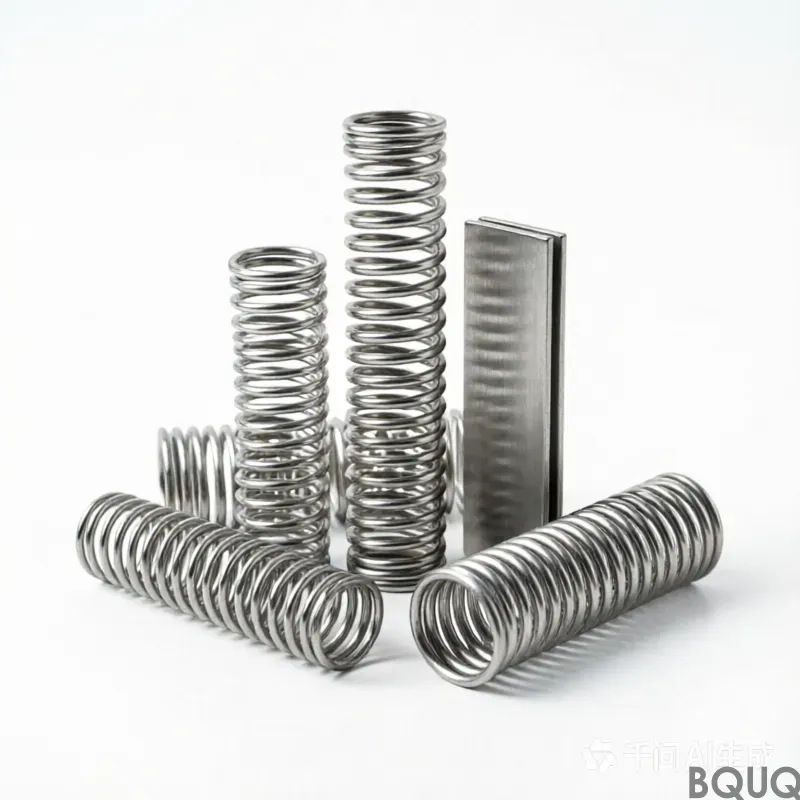
BQUQ is a professional metal spring manufacturer, please send us drawings, and our company will quote you within 12 hours.