
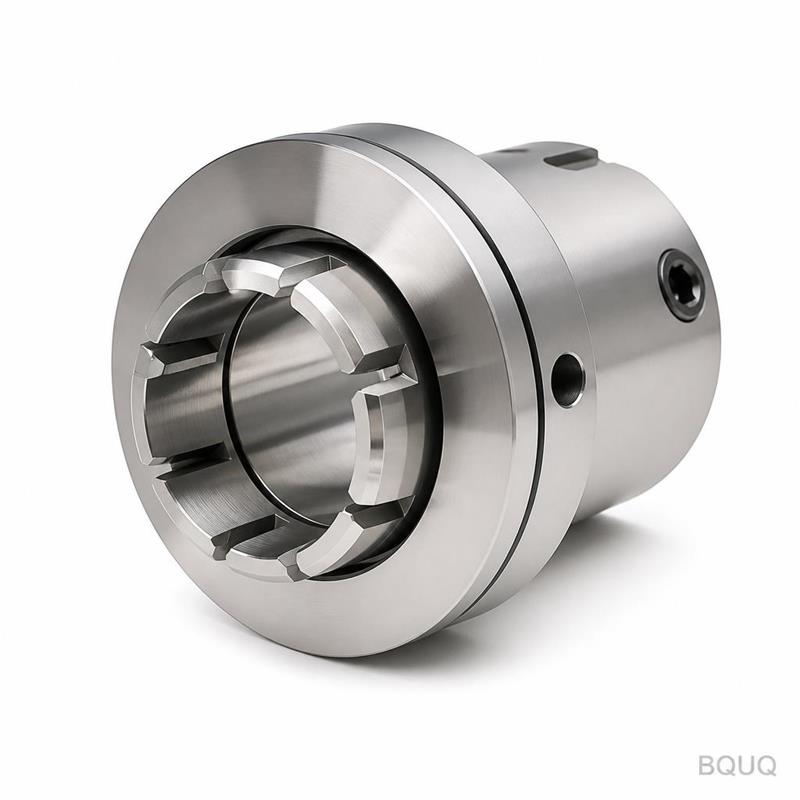
Live Tooling in CNC Turning: Milling on a Lathe
Short answer: live tooling turns a CNC lathe into a turning center that can mill, drill, tap and slot without a second setup. A part with six milled flats, a cross-hole and a tapped end face can be finished in one cycle, holding ±0.005 mm on turned diameters and roughly ±0.02 mm on milled features. Live tooling wins when your part is round-first and mill-second — it typically cuts 15–40% off the cost of splitting the job across a lathe and a mill, but only when the geometry actually suits it.
Most parts are not purely round and not purely flat. A motor shaft has a turned journal, a milled keyway and a tapped end. A hydraulic fitting has a thread, a hex and a cross-drilled port. If you turn the round features on a lathe and then re-fixture for the milled features, you pay twice for setup, and every re-clamp adds another layer of stack-up error. Live tooling exists to delete that second setup.
What Is Live Tooling on a CNC Lathe?
Live tooling — also called driven tooling — is a tool holder on the lathe turret that carries its own motor and spins an end mill, drill or tap while the main spindle either stops, indexes or rotates slowly. A standard lathe tool is stationary and cuts because the workpiece spins. A live tool spins its own cutter, so the lathe can perform milling operations the way a machining center does. The enabler is the C-axis: the main spindle becomes a programmable rotary axis that can hold an angular position, so a flat milled by the live tool lands at a known angle relative to the part datum. Without the C-axis, live tooling would have no way to index to the right face.
C-Axis vs Y-Axis Live Tooling
This is the single biggest distinction in lathe milling, and it changes what parts you can make.
A C-axis-only machine approaches the part radially. You can drill and tap on the diameter and mill flats, but you cannot move the cutter off the machine centerline, which limits pockets and eccentric features. A Y-axis turret moves up and down off-centre, so the cutter can be positioned anywhere across the face of the part. That unlocks pockets, slots and flats that do not run through the centerline, and it removes the awkward workaround of faking off-centre features by interpolating X and C together. A B-axis mill-turn head swivels and adds angled features and near-five-axis contouring in one setup.
| Configuration | Milling freedom | Typical feature tolerance | Best-fit parts |
|---|---|---|---|
| 2-axis lathe + second op on a mill | Unlimited on the mill | ±0.02–0.05 mm after re-fixture | Low volume, complex milling |
| C-axis live tooling | Radial drilling/tapping, flats | ±0.02–0.03 mm | Cross-holes, hexes, simple flats |
| Y-axis live tooling | Off-centre pockets, slots, flats | ±0.01–0.02 mm | Most round-first parts with milling |
| B-axis mill-turn | Angled and contoured features | ±0.005–0.01 mm | High-value single-setup parts |
What Can Live Tooling Actually Do?
The operation list is broader than most buyers expect. Here is what a well-set-up live-tool lathe handles, and what it realistically holds.
| Operation | Typical tolerance | Notes |
|---|---|---|
| Cross-drilling on the diameter | ±0.05 mm position | Easier with Y-axis; needs a flat or spot first |
| Axial drilling on the end face | ±0.02 mm position | Spot-drill to stop walk |
| Milling flats or hex | ±0.02 mm across flats | C-axis indexing sets the angle |
| Slotting | ±0.02 mm width | Cutter diameter and rigidity dominate |
| Power tapping | Class 6H typical | Rigid tapping avoids tap drift |
| Face engraving or marking | Cosmetic | Free capacity, no second setup |
One rule matters above all: keep the milling stock light. A live tool holder is less rigid than a mill spindle, so heavy milling takes many shallow passes and wears cutters fast. When a feature needs serious metal removal, a real mill is still the honest answer. The second rule is to plan tool changes. Each driven holder occupies a turret station, and if a part needs four different live tools you may run out of stations before you run out of features. Good programmers group operations by tool, not by drawing order, so the C-axis indexes as few times as possible.
When Live Tooling Beats a Separate Mill
Live tooling wins when the milled features are secondary to a part that is fundamentally turned. The value is setup elimination and datum integrity, not raw milling horsepower. If a part is round with a few small milled details, one live-tool cycle beats two operations on two machines on both cost and accuracy. If the part is a flat block with a single drilled bore, a mill is cheaper and simpler. The crossover is usually where milling time on the lathe would exceed roughly a quarter of the total cycle.
There is also a quality argument. Every time a part leaves a chuck and gets re-clamped, you inject a new alignment error. Concentricity between a turned diameter and a milled bore is far easier to control when both are cut in the same clamping. Buyers chasing true position between round and flat features should ask their supplier to quote the part as a single live-tool operation before accepting a two-machine plan.
A worked example makes the economics clearer. Suppose a 40 mm stainless shaft needs a 6 mm cross-hole, two milled flats and a tapped M5 end. As two operations, that is a lathe setup, a mill fixture, two handlings and two inspection points. As one live-tool cycle, it is a bar in, a finished part out, with the cross-hole and flats sharing the same datum as the turned diameters. At a few hundred pieces the difference in setup labour alone usually pays for the higher machine rate, and the scrap rate from re-clamping drops with it.
Accuracy and Surface Finish Notes
Turned diameters on a good lathe reach ±0.005 mm and Ra 0.8 µm without drama. Live-tooled milled features are looser — think ±0.02 mm and Ra 1.6 µm — because the tool holder is less rigid and the effective tool overhang is longer. Interrupted cuts from cross-holes or flats make chatter more likely, so feeds are set conservatively. If a drawing calls for ±0.005 mm on a milled pocket, that is genuinely hard on live tooling and a mill is the defensible route. Be suspicious of any shop that promises mill-grade tolerance on a driven tool without seeing the drawing.
Surface finish on live-tooled faces also depends on the cutter path. A face mill run in one pass leaves a cleaner flat than an end mill stepped across the same width. For cosmetic flats, ask for a finishing pass with a sharp cutter and a light depth of cut. For functional locating flats, prioritise flatness and position over cosmetic finish — a slightly visible tool path on a mounting face does not affect how the part performs, and paying for a cosmetically perfect hidden face is money spent on nothing.
Cost and Cycle Time: the Real Trade-Off
Live tooling is not free. The tool holders cost more, programming is more involved, and the machine rate is higher. What you get back is one setup instead of two, less handling, fewer fixtures and tighter datum control. For a part at 500–5,000 pieces, that difference typically lands in the 15–40% range on unit cost. At prototype quantity the setup saving is proportionally larger, but the programming overhead can erase it.
The cleanest way to decide is to ask two questions. First, what fraction of the part's cycle is milling? Second, how tight is the relationship between the turned and milled features? High milling content and loose relationships favour a mill or mill-turn. Low milling content and tight relationships favour live tooling. Send us the drawing and we will quote both routes rather than quietly pick the one that fills our schedule.
Design Rules for Live-Tooled Parts
Keep these in mind and a turnaround shop can quote you confidently. Minimise the number of part faces that need milling, because each face consumes a C-axis index and often a tool change. Avoid very deep pockets that need long small-diameter cutters — they chatter and snap. Give yourself a clear datum; a turned shoulder makes an excellent reference for the milled features. Specify live-tooled milling tolerances honestly rather than defaulting every feature to ±0.005 mm, because over-tolerance is pure overhead. And if the part truly needs heavy milling, design it as a milled part and stop trying to force it onto a lathe.
Frequently Asked Questions
Q: Is live tooling the same as a mill-turn machine?
A: No, though they overlap. Live tooling means a motorised tool on the turret of a lathe, usually with a C-axis. A true mill-turn machine has a B-axis or a second spindle and can approach the part from more angles with far more milling power. If your part is mostly turned with light milling, live tooling is the cheaper tool; if it is genuinely five-axis work, you want the mill-turn.
Q: What tolerance can live tooling hold on milled features?
A: Budget ±0.02 mm on milled flats and pockets and ±0.05 mm on cross-hole position for a normal job. Tight, well-supported features can reach ±0.01 mm, but live tooling is less rigid than a mill, so treat sub-±0.01 mm milling as a special request rather than a default. Turned diameters still hold ±0.005 mm.
Q: How much does live tooling save versus two setups?
A: Typically 15–40% at 500–5,000 pieces, driven by setup elimination and less handling. The saving comes from removing a second machine, a second fixture and a second clamping, not from the lathe cutting faster. At very low volume the programming overhead can outweigh the setup saving, so volume matters.
Q: Can you mill a keyway with live tooling?
A: Yes. A slot or keyway on a shaft is one of the most common live-tool jobs, held around ±0.02 mm for width. For long keyways or tight side-wall tolerance, a mill with a proper stub cutter may be more reliable, and we will say so on the quote instead of forcing it onto the lathe.
Q: What drawing detail do you need to quote live-tooled parts?
A: A STEP file or a dimensioned 2D drawing, the material, quantity, finish and any true-position callouts between the round and milled features. Those relationship callouts are what decide whether the part belongs on a live-tool lathe or a mill. Send them to sc@bquq.com and we return a quote within 12 working hours.
Related Resources
- CNC turning vs milling: choosing the right process — how to decide when a part belongs on a lathe, a mill, or both.
- CNC machining services — turning, milling and single-setup lathe work from a Dongguan source factory.
- About BQUQ — an ISO9001 source factory running CNC, stamping, spring and heat sink lines under one roof.
- Contact us — send your drawing for a quote within 12 working hours.
Authored by the BQUQ Engineering Team. BQUQ is an ISO9001-certified source factory in Dongguan, China, running CNC machining, metal stamping, custom springs, heat sink and collet lines under one roof. Send drawings to sc@bquq.com or WhatsApp +86 13713157787 for a quote within 12 working hours. www.bquq.com


