
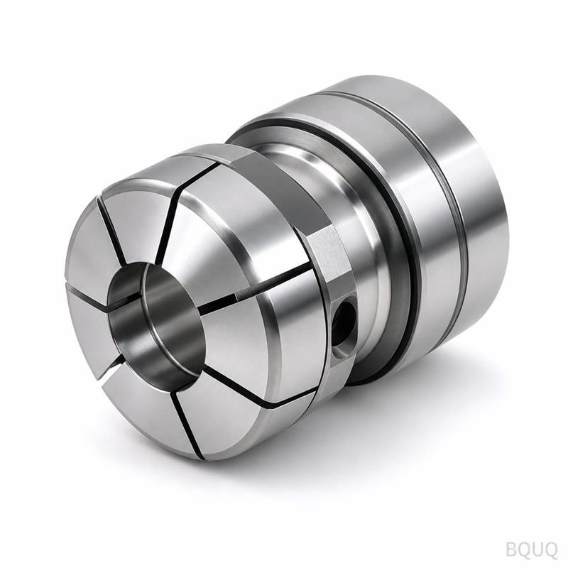
CNC Machining Fluid and Pneumatic Connectors
Short answer: CNC machining produces fluid and pneumatic connectors by turning the body and thread, then milling cross-ports, hex flats or mounting pads to a sealed, repeatable geometry. Typical shop capability is ±0.005 mm on critical diameters, Ra 0.4–0.8 µm on sealing faces, and thread gauging to ISO 228 or SAE J1926. Bodies are usually 6061-T6 aluminum, 303/316 stainless or C3604 brass. Lead time for a first article is typically 5–10 working days after drawing release; BQUQ returns a quote in 12 working hours and holds flexible MOQ, so a 50-piece pilot run is realistic before tooling or volume commitments.
Connectors look simple on a drawing and cause disproportionate trouble in the field. A pneumatic fitting that weeps at 8 bar, a hydraulic adapter that seizes after 200 thermal cycles, a manifold port that leaks only on one of six cavities — these are machining and specification problems, not assembly problems. This article covers how to specify, machine and inspect fluid and pneumatic connectors so the part behaves the same on piece 1 and piece 10,000.
What counts as a fluid or pneumatic connector?
In machining terms, a connector is any part whose job is to join two fluid paths — liquid or gas — while holding pressure and preventing leakage. That covers a wide family, and the machining strategy changes with each.
| Family | Typical function | Dominant machining process | Critical feature |
|---|---|---|---|
| Barbed hose fitting | Push-on flexible hose, low pressure | Turning + knurl/barb form | Barb crest diameter, lead-in chamfer |
| Push-to-connect fitting | Instant tube connection, pneumatics | Turning + milling (release slot) | Bore roundness, O-ring groove depth |
| JIC / SAE flare fitting | Hydraulic, high pressure | Turning, 37° or 45° cone | Cone angle and surface finish |
| ORFS / O-ring boss | Hydraulic, face seal | Turning + face grooving | Groove width, face flatness |
| Banjo / banjo bolt | Restricted-space hydraulic | Turning + cross-drilling | Cross-hole deburr, flow area |
| Manifold block | Distributes multiple circuits | Milling + drilling + tapping | Port-to-port position, thread depth |
| Quick-disconnect coupler body | Frequent connect/disconnect | Turning + milling + grinding | Sleeve bore, seal land concentricity |
The common thread: every one of these parts is defined by a sealing interface. Everything else — hex flats, wrench clearance, hose barb geometry, mounting ears — is secondary. If you only hold one thing tightly, hold the seal.
Which materials should you choose for connectors?
Material choice is driven by media, pressure, temperature and cost, in that order. Compatibility with the working fluid matters more than strength in most low-pressure pneumatic work.
| Material | Best for | Pressure suitability | Notes |
|---|---|---|---|
| 6061-T6 aluminum | Pneumatics, low-pressure hydraulics, air tools | Low to medium | Anodize for corrosion; avoid bare aluminum with caustic media |
| 2024 aluminum | Higher-strength aerospace fittings | Medium to high | Poor corrosion resistance uncoated; usually plated |
| C3604 brass | Air, water, inert gas, general pneumatics | Low to medium | Excellent machinability, natural corrosion resistance |
| 303 stainless | Water, mild chemicals, food-adjacent lines | Medium | Free-machining; slightly lower corrosion resistance than 316 |
| 316/316L stainless | Aggressive chemicals, marine, medical gas | Medium to high | Harder to machine; specify sharp tooling and slower feeds |
| Carbon steel (12L14, 1215) | High-pressure hydraulic adapters | High | Requires zinc/nickel plating; plating thickness affects threads |
| PPSU / PEEK (machined plastic) | Insulating, lightweight, chemically inert | Low to medium | Machined, not molded, for low volumes |
Two practical rules. First, never mix a bare aluminum body with a stainless steel mating thread in a wet environment — galvanic corrosion will seize the joint. Use a plated body, an anti-seize compound, or a plastic isolator. Second, when a customer specifies "stainless" for a pneumatic line running dry instrument air, 303 is usually sufficient and machines roughly 30–40% faster than 316, which shows up directly in unit price.
How do you machine a connector that actually seals?
Sealing performance is created by three things: seal geometry, surface finish and concentricity. All three are machining decisions.
Sealing face geometry
For an O-ring boss port, the groove depth and width control the squeeze percentage. A typical target is 15–25% squeeze on the O-ring cross-section. If the groove is 0.05 mm too deep, the O-ring never loads; 0.05 mm too shallow and it extrudes under pressure. This is a tolerance you must call out explicitly, not leave to general tolerances.
For flare fittings, the cone angle is the seal. A 37° JIC cone held to ±0.5° and a surface finish of Ra 0.8 µm or better will seat reliably. A cone machined at 38° with a torn finish will leak at high pressure no matter how hard the assembler tightens it.
Surface finish on sealing surfaces
| Sealing method | Typical required finish | Why |
|---|---|---|
| O-ring face seal | Ra 0.4–0.8 µm | Prevents seal extrusion and leak paths |
| Flare cone (JIC/SAE) | Ra 0.8 µm or better | Metal-to-metal contact must be continuous |
| Thread sealant (NPT) | Ra 1.6 µm acceptable | Thread deformation does the sealing |
| Bonded washer / Dowty | Ra 1.6 µm acceptable | Washer deforms to fill surface |
| Gasket face (flange) | Ra 1.6–3.2 µm | Gasket conforms; too smooth can be worse |
Note the last row. For soft gasket joints, an extremely polished face is not automatically better — some surface texture helps the gasket bite. Over-specifying finish adds cost without adding seal integrity.
Concentricity and thread-to-bore alignment
On a push-to-connect fitting, the tube bore and the thread must share an axis. If they run out by more than about 0.05 mm, the tube enters at an angle, the collet grips unevenly, and the fitting leaks or releases under vibration. The fix is process, not inspection: turn the body, bore and thread in a single setup, or use a collet chuck that holds the turned OD as the datum for the second operation. BQUQ runs collet chuck systems for exactly this reason — re-chucking on a three-jaw scroll chuck typically adds 0.03–0.08 mm of runout, which is enough to fail a pneumatic leak test.
Deburring internal cross-ports
Cross-drilled ports intersect the main bore and leave a burr ring at the intersection. That burr sheds particles into the fluid path and can prevent a seal from seating. Specify deburring explicitly — thermal deburring, abrasive flow, or controlled manual deburring with a bore scope check. "Deburr all edges" on a drawing is too vague; state which edges and to what standard.
Threads: where most connector failures start
Threads on connectors are not fasteners. They are pressure boundaries, and they follow different standards.
- NPT / NPTF (tapered): seals by thread deformation. Requires sealant or tape. Do not mix NPT and NPTF expectations — NPTF is the dry-seal variant and needs tighter tooling control.
- G / BSPP (parallel): seals with a bonded washer or O-ring, not the thread itself. Common in European pneumatic equipment.
- UNF / SAE J1926 (straight thread O-ring boss): seals on an O-ring at the base of the thread. Position of the O-ring seat is critical.
- Metric parallel (ISO 6149): similar principle to SAE ORB, metric dimensions.
- JIC 37° flare: seals on the cone, thread provides clamping force only.
A frequent and expensive mistake is specifying a tapered thread where a parallel thread with an O-ring was intended, or vice versa. The parts look similar in a photo and are incompatible in service. Always state the full standard on the drawing, not just "1/4 inch."
Thread inspection should be by gauge, not by caliper. Go/no-go ring gauges for external threads and plug gauges for internal threads catch pitch diameter and lead errors that a caliper cannot see. BQUQ gauges connector threads against the specified standard and records the result per lot.
Design-for-manufacturing rules that cut connector cost
Most connector cost is in setup and secondary operations, not in material. A few changes usually pay for themselves.
1. Consolidate to one thread standard per assembly. Mixed NPT and BSPP ports on the same manifold force two tooling sets, two gauge sets and two inspection routines.
2. Avoid deep, small-diameter cross-holes. A cross-hole with a depth-to-diameter ratio above 6:1 requires peck drilling, tends to drift, and is hard to deburr. Reorient the port if the design allows.
3. Specify hex flats to a standard wrench size. Custom hex dimensions add milling time and give the field technician no standard tool to use.
4. Keep seal grooves out of interrupted cuts. A groove that crosses a milled flat or cross-hole will have a burr at every interruption.
5. Use one datum for sealing features. If the O-ring groove and the mounting face are dimensioned from different datums, tolerance stack-up will eventually produce a leaker.
6. Tolerances only where they matter. General tolerances of ±0.1 mm on non-sealing features and ±0.005 mm on sealing diameters is a normal, cost-effective split. Tightening everything to ±0.005 mm can multiply machining time with no functional gain.
For a deeper look at how tolerance choices cascade into cost, see our breakdown of DFM redesign examples.
Inspection and leak testing
A connector that measures correctly can still leak, so dimensional inspection and functional testing are both required.
| Check | Method | Typical frequency |
|---|---|---|
| Thread form and pitch diameter | Go/no-go gauges | 100% or per AQL |
| Seal groove depth/width | Optical comparator, CMM | First article + sampling |
| Bore roundness and concentricity | CMM, air gauge | First article + sampling |
| Surface finish on seal faces | Profilometer | First article + periodic |
| Burr-free internal ports | Bore scope, visual | Per lot |
| Leak integrity | Air decay test or hydrostatic | Per lot or 100% for critical parts |
Air decay testing at 1.5× working pressure is the standard production screen for pneumatic fittings. For hydraulic parts, hydrostatic proof testing to 1.5–2× rated pressure is common. Both are destructive to nothing but the schedule — budget test time into the lead time rather than treating it as an afterthought.
If you are specifying cutting fluids for machining these parts, particularly stainless and brass, our guide to cutting fluid selection covers the media-compatibility angle, which matters when residual fluid on a connector body could contaminate a gas line.
Why source connectors from a single factory?
Connectors are rarely a single process. A typical pneumatic fitting needs turning, milling for the release slot or mounting pad, thread rolling or cutting, deburring, surface treatment and leak testing. When those steps sit in different suppliers, the tolerance stack-up crosses company boundaries and nobody owns the final seal.
Running turning, milling, deburring and inspection under one roof in Dongguan means the datum established on the lathe is the datum used at final inspection. BQUQ operates four production lines in one ISO9001 factory covering CNC machining to ±0.005 mm, metal stamping, custom springs and heat sink production. For connector work, the relevant capability is turning and milling on the same floor, with collet chuck workholding for concentricity and gauge-based thread verification.
For buyers, the practical benefit is a shorter loop between "it leaks" and "here is why." For engineers, it is a single point of accountability for the sealing interface.
Explore the relevant processes: CNC machining, CNC turning parts and CNC milling parts. If your connector is threaded into a machined housing, our notes on thread specifications cover the mating-side requirements.
Frequently Asked Questions
Q: What tolerance should I specify on a connector seal groove?
A: Groove depth and width should be toleranced directly, typically ±0.025 mm or tighter depending on O-ring cross-section and pressure. Do not rely on general tolerances for seal features. Squeeze percentage of 15–25% is the usual target. State the groove dimensions as basic dimensions referenced to the O-ring standard you are designing to, and let the machinist hold them independently of the rest of the part.
Q: Can CNC machining produce pneumatic push-to-connect fittings economically at low volume?
A: Yes. Below roughly 5,000–10,000 pieces per year, machining is usually cheaper than injection molding once tooling amortization is included. BQUQ holds flexible MOQ, so a 50–500 piece pilot run is practical. The main cost drivers are the number of setups, the release-slot milling operation, and whether you require 100% leak testing or sampling.
Q: Which is better for hydraulic connectors, 316 stainless or plated carbon steel?
A: It depends on the environment, not the pressure. Plated carbon steel handles high pressure well and costs less, but plating can chip at thread edges and expose bare steel to corrosion. 316 stainless resists aggressive media and marine conditions but machines slower and costs more. For most indoor hydraulic systems, plated carbon steel is the economical choice; specify 316 for chemical, offshore or washdown duty.
Q: How do I prevent galvanic corrosion between an aluminum body and a stainless mating part?
A: Separate the metals or control the environment. Options include hard-anodizing the aluminum body, specifying a stainless grade with a plated aluminum insert, applying an anti-seize compound at assembly, or using a plastic isolator washer. In wet or salt-exposed service, avoid direct bare aluminum-to-stainless contact entirely, since the aluminum will corrode preferentially at the joint.
Q: What lead time should I expect for a first article connector?
A: For a straightforward turned fitting with one secondary milling operation, a first article typically takes 5–10 working days after drawing release, including material procurement and inspection. Manifolds with multiple ports and leak testing run longer. BQUQ returns quotations in 12 working hours, so the drawing review and DFM feedback loop starts the same day you send files.
Related Resources
- About BQUQ and the Dongguan factory: /about/
- CNC machining, turning and milling capabilities: /cnc-machining/
- More technical articles for design engineers: /bquq-blog/
- Industry trends in precision manufacturing: /industry-dynamics/
- Common sourcing and tolerance questions: /faq/
- Project case studies: /case/
- Send drawings for a 12-hour quote: /contact/
Authored by the BQUQ Engineering Team. BQUQ (Dongguan) runs CNC machining (±0.005 mm), metal stamping, custom springs, and heat sink production in one ISO9001 factory. Source-direct from Dongguan, China — quote in 12 hours: sc@bquq.com | WhatsApp +86 13713157787 | www.bquq.com


