
Choosing a TIM: Grease, Pad, Gap Filler and Phase Change
Short answer: Match the TIM to your gap, your pressure and your production line. For a lapped metal-to-metal joint under 0.05 mm gap and real clamping force, use thermal grease at 1–6 W/m·K and 0.02–0.05 mm bond line. For gaps of 0.2–1.0 mm with light or uneven pressure, use a soft gap filler at 1.5–6 W/m·K. For 0.5–2.0 mm gaps on a reworkable assembly line, use a thermal pad at 1–8 W/m·K. For high-volume, pump-out-prone applications, use a phase change material at 3–8 W/m·K that thins above roughly 45–60 °C. Bulk conductivity matters less than bond line thickness and contact pressure.
Why the TIM is often the weakest link in the thermal stack
Engineers spend weeks optimizing fin geometry and airflow, then bolt the heat sink down with whatever interface material was already in the drawer. That is backwards. In a typical forced-air assembly, the interface can account for 30–60% of total thermal resistance from junction to ambient, even though it occupies less than a millimeter of the stack.
The reason is simple geometry. Thermal resistance through a layer equals thickness divided by (conductivity × area). A 0.05 mm grease layer at 3 W/m·K over a 30 × 30 mm footprint contributes roughly 0.02 °C/W. Swap in a 1.0 mm pad at the same bulk conductivity and you get about 0.37 °C/W — nearly twenty times worse, from the same "3 W/m·K" datasheet number.
That is why the useful question is never "which TIM has the highest W/m·K?" It is "what is the thinnest, most complete, most stable layer I can create between these two surfaces, given how they are made and how they are assembled?"
The three variables that actually decide the answer
1. Gap. Measured, not assumed. Total gap includes surface roughness, flatness error, and any mechanical standoff or solder-mask step.
2. Contact pressure and its distribution. A screw in each corner of a stiff base plate behaves very differently from a plastic clip on a thin substrate.
3. Life and rework. Pump-out, dry-out, and whether a field technician will ever open the unit again.
How do I measure the real gap before choosing a TIM?
Do not trust CAD. Measure the assembled stack. A practical method: assemble the heat sink with a thin strip of pressure-sensitive film or soft shim stock at several points, torque to spec, disassemble, and read the witness marks. On production parts, a simpler proxy is to measure base flatness and substrate flatness separately and add them.
For a CNC-machined aluminum or copper base held to ±0.005 mm on thickness and a flatness spec, the metal-to-metal gap is usually dominated by surface finish and substrate warpage rather than by the base itself. That is exactly the situation where a thin grease or phase change layer wins. If you are still specifying flatness loosely, our guide to heat sink flatness specs covers how to set a number that a supplier can actually hold.
Gap bands and the TIM that fits
| Measured gap | Typical TIM | Bond line | Pressure needed | Indicative conductivity |
|---|---|---|---|---|
| < 0.05 mm | Thermal grease | 0.02–0.05 mm | High, uniform | 1–6 W/m·K |
| 0.05–0.20 mm | Phase change material | 0.03–0.08 mm | Medium-high | 3–8 W/m·K |
| 0.20–1.0 mm | Soft gap filler (dispensed) | Fills as-is | Low to medium | 1.5–6 W/m·K |
| 0.5–2.0 mm | Thermal pad | 0.5–2.0 mm | Low, forgiving | 1–8 W/m·K |
| > 2.0 mm | Gap filler + mechanical shim | Varies | Low | 1–4 W/m·K |
Treat the conductivity ranges as indicative market bands, not guarantees. Always validate with your own stack-up test.
Grease, pad, gap filler, phase change: how do they compare?
Thermal grease
Grease is still the best performer per unit thickness. It wets microscopic asperities, displaces air, and can be spread to a bond line thinner than a human hair. Its weaknesses are mechanical: it can pump out under thermal cycling as the joint breathes, it can dry out over years, and it is messy on a production line. Grease is the right answer for high-power, well-clamped, non-reworkable assemblies with a flat base and a stiff substrate. If your product sees wide thermal swings, read our analysis of TIM pump-out before you commit.
Thermal pads
Pads are the production engineer's friend. They are clean, pre-cut, thickness-controlled, and forgiving of uneven pressure and moderate warpage. The cost is thermal: you cannot go below the manufactured thickness, and soft pads compress only 10–30% under normal loads. Use pads where the gap is genuinely 0.5 mm or more, where pressure is low or uneven, or where the assembly must be reworkable. For thin gaps, a pad is a downgrade dressed up as a convenience.
Gap fillers
Dispensed gap fillers sit between grease and pads. They flow to fill irregular cavities, cure or stay soft in place, and handle gaps from about 0.2 mm to several millimeters. They shine on multi-component assemblies — a board with several different component heights sharing one heat sink — because one dispense pattern can serve all of them. They require dispensing equipment and a cure or settling step, which adds process complexity.
Phase change materials
Phase change materials are solid at room temperature and thin out above roughly 45–60 °C. That gives you dry, clean handling during assembly and a grease-like bond line in operation. They are the standard choice for high-volume CPU, GPU, and power-module interfaces where pump-out resistance and consistent application matter more than the last 0.01 °C/W.
Side-by-side comparison
| Property | Grease | Pad | Gap filler | Phase change |
|---|---|---|---|---|
| Best gap range | < 0.05 mm | 0.5–2.0 mm | 0.2–3 mm | 0.05–0.2 mm |
| Thermal performance | Best | Fair | Good | Very good |
| Assembly cleanliness | Poor | Excellent | Fair | Excellent |
| Reworkability | Difficult | Easy | Difficult | Moderate |
| Resistance to pump-out | Low | High | High | High |
| Process cost | Low material, high labor | Lowest | Dispensing equipment | Low |
| Thickness control | Operator-dependent | Factory-controlled | Dispense-dependent | Factory-controlled |
Does higher W/m·K always mean better cooling?
No. Bulk conductivity is one term in a product of three. The others are bond line thickness and contact area, and both are usually worse than the datasheet implies.
Consider two candidates for a 25 × 25 mm interface at 20 psi:
- Grease at 3 W/m·K, 0.03 mm bond line → about 0.019 °C/W
- Pad at 6 W/m·K, 1.0 mm thick → about 0.27 °C/W
The pad has double the conductivity and fourteen times the resistance. Marketing materials rarely put those two numbers on the same page.
There is also a real trade-off inside each family. Filling a grease or gap filler with more conductive particles raises viscosity and lowers the minimum achievable bond line, so a 6 W/m·K grease may actually underperform a 3 W/m·K grease if the operator cannot spread it thin. The same logic applies to pads: harder, more highly filled pads resist compression, so a soft 3 W/m·K pad can beat a stiff 6 W/m·K pad at low pressure.
Where the heat sink itself sets the ceiling
No TIM can rescue a base that is not flat or a heat sink that cannot spread heat. If your spreading resistance is already high, interface improvements produce diminishing returns. Base thickness and material choice often matter more than the last W/m·K — see our heat sink base thickness guide for the trade-offs between copper and aluminum bases.
How do I specify a TIM on a drawing or spec sheet?
Put five things on the drawing, and put them in this order:
1. Interface material and thickness, with a tolerance. "Thermal pad, 1.0 mm ±0.1 mm, 3 W/m·K minimum" is a spec. "Thermal pad" is a wish.
2. Contact pressure or mounting torque, plus the fastener pattern. Pressure distribution matters as much as the average.
3. Surface finish and flatness of the mating face. These determine whether a thin bond line is even possible.
4. Operating temperature range and cycle count, so the supplier can assess pump-out and dry-out risk.
5. Acceptance test. A defined thermal test at a defined power and airflow, with a pass/fail delta.
Our thermal spec sheet checklist walks through the full document if you want a template.
A note on surface finish
A machined base at Ra 0.8 µm gives grease something to wet and still allows a thin layer. A rough, as-cast or as-extruded surface forces you into a thicker, more compliant TIM. If you are choosing between an extruded profile with minimal machining and a fully CNC-machined base, the machining cost often pays back in TIM savings and junction temperature margin.
Practical selection rules for common applications
| Application | Recommended TIM | Why |
|---|---|---|
| High-power IGBT, clamped | Grease or phase change | High pressure, thin bond line, flat base |
| LED module on extruded heat sink | Pad or gap filler | Moderate gap, moderate pressure, reworkable |
| Multi-height board, one heat sink | Dispensed gap filler | One pattern covers varying component heights |
| Consumer electronics, high volume | Phase change | Clean handling, pump-out resistance |
| Field-serviceable unit | Pad | Removable and replaceable without cleaning |
| Wide thermal cycling, bolted joint | Phase change or soft gap filler | Resists pump-out and dry-out |
These are starting points. Every one of them should be confirmed by a thermal test on the actual assembly, at the actual mounting torque, in the actual orientation.
Why the heat sink supplier matters to your TIM decision
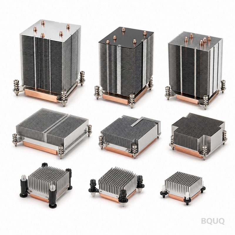
TIM performance is a system property, and half the system is the heat sink. Base flatness, surface finish, standoff height, and mounting-hole position all determine what interface material is even viable. A supplier who machines to ±0.005 mm and controls flatness gives you the option of a thin, high-performance interface. A supplier who ships a warped base forces you into a thick pad and a hotter junction.
BQUQ runs four production lines in one Dongguan factory — CNC machining, metal stamping, custom springs, and heat sink production — under ISO9001. That means base machining, fin bonding, and finishing happen under one quality system, so the interface surface you specified is the interface surface you receive. Flexible MOQ supports prototype and pilot builds, and quotes come back in 12 working hours. Send your stack-up and thermal target to sc@bquq.com or WhatsApp +86 13713157787.
Frequently Asked Questions
Q: Can I use thermal grease with a thermal pad to get the best of both?
A: No — stacking them usually makes things worse. The pad holds the layers apart and prevents the grease from reaching a thin bond line, so you get the pad's thickness plus the grease's mess. Pick one. If the gap is small and pressure is high, use grease alone. If the gap is large or pressure is uneven, use a compliant pad or gap filler alone.
Q: How much does mounting pressure change TIM performance?
A: Substantially. Going from light finger pressure to a properly torqued joint can cut interface resistance by half or more, because pressure squeezes out excess material and closes the bond line. The gain is largest for greases and soft gap fillers, smaller for hard pads. Always specify a torque value and a fastener pattern, and verify the pressure distribution across the base.
Q: When should I choose a phase change material over grease?
A: Choose phase change when the joint sees repeated thermal cycling, when you need clean dry handling on a production line, or when pump-out has already caused field failures. It performs close to grease in steady state while resisting migration. Choose grease when you need the absolute lowest thermal resistance and the assembly is well clamped and not expected to be serviced.
Q: Do I need a different TIM for a copper base than an aluminum base?
A: The TIM choice is mostly driven by gap, pressure, and flatness rather than base material. That said, copper and aluminum expand at different rates, so a copper base bonded to an aluminum or ceramic substrate will move more under thermal cycling. That increases pump-out risk and typically pushes you toward a phase change material or a soft gap filler rather than plain grease.
Q: How do I test whether my TIM choice is actually working?
A: Measure junction or case temperature at a fixed power, airflow, and ambient, then compare against your thermal model. A useful check is to run the same assembly with two different TIMs and compare the delta — if the difference is smaller than your measurement noise, the interface is not your bottleneck. Instrument the base and the substrate separately to see where the drop occurs.
Related Resources
- About BQUQ and our Dongguan manufacturing footprint: /about/
- Heat sink product range, including extruded and machined bases: /heat-sinks/
- Industry trends in electronics cooling: /industry-dynamics/
- Full technical article library: /bquq-blog/
- Frequently asked questions on sourcing and specs: /faq/
- Case studies from production programs: /case/
- Request a quote or send your drawing: /contact/
Authored by the BQUQ Engineering Team. BQUQ (Dongguan) runs CNC machining (±0.005 mm), metal stamping, custom springs, and heat sink production in one ISO9001 factory. Source-direct from Dongguan, China — quote in 12 hours: sc@bquq.com | WhatsApp +86 13713157787 | www.bquq.com


