
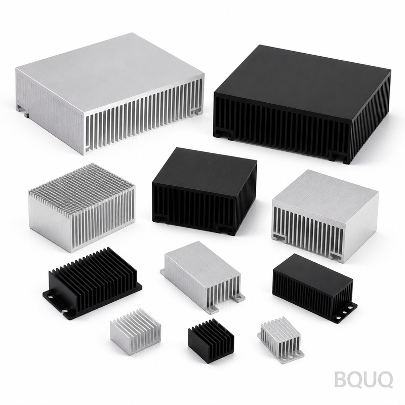
Heat Sink Base Thickness: Spreading Resistance Explained
Short answer: Heat sink base thickness controls spreading resistance — the penalty for forcing heat from a small source into a much larger fin field. Too thin and the base cannot spread heat laterally, so outer fins starve; too thick and you add conduction resistance plus mass without gaining spreading. For a typical 20–40 mm source on an aluminium base, the sweet spot is usually 4–8 mm, with copper bases often 30–50% thinner for the same spreading. The correct number depends on source size, base area, heat flux and airflow, so it should be calculated, not copied. BQUQ machines bases to ±0.005 mm and quotes custom heat sinks in 12 working hours.
What Spreading Resistance Actually Is
Every heat sink has a thermal resistance network. Heat leaves the die or component, crosses the thermal interface material, enters the base plate, spreads laterally through the base, then travels up the fins and finally into the air. Most engineers size the fin stack carefully and then treat the base as a passive slab. That is where designs go wrong.
Spreading resistance is the extra resistance created when heat must move sideways through the base material to reach fins that are not directly above the source. If your heat source is 15 mm × 15 mm and your heat sink footprint is 80 mm × 80 mm, roughly 96% of the base area is not in the direct conduction path. Heat has to fan out laterally, and that fan-out is not free.
The total base contribution is therefore:
R_base = R_1D + R_spread
Where R_1D is the simple one-dimensional conduction through the base thickness (t / (k × A_source)) and R_spread is the lateral spreading term. R_1D grows linearly with thickness. R_spread falls as thickness grows, but with sharply diminishing returns. The optimum thickness is where the sum is minimised — and that minimum is usually flatter than people expect.
Why thin bases fail
A 2 mm aluminium base under a 25 mm square IGBT footprint looks efficient on paper: short conduction path, low mass. In practice, the base cannot move heat to the corners of the heat sink. The centre fins run hot, the outer fins run cool, and the effective fin area you paid for is wasted. Measured case temperatures can be 8–15 °C higher than a simulation that assumes an isothermal base.
Why very thick bases fail too
Going to 15 mm of aluminium adds mass, cost, machining time and — critically — 1D conduction resistance. Aluminium conducts at roughly 200 W/m·K, so every extra millimetre of base under a 25 mm source costs about 0.008 °C/W. That sounds trivial, but at 100 W it is 0.8 °C of pure loss, and it buys almost no additional spreading once the base is already thick enough.
The Optimum Base Thickness: A Practical Table
The table below gives indicative optimum base thicknesses for aluminium (k ≈ 200 W/m·K) and copper (k ≈ 390 W/m·K) bases, assuming a single central source and a base footprint 2.5–4× the source dimension. Treat these as starting points for simulation, not as specifications.
| Source footprint | Base footprint | Aluminium optimum | Copper optimum | Notes |
|---|---|---|---|---|
| 10 × 10 mm | 40 × 40 mm | 3–4 mm | 2–3 mm | Small die, high flux; consider copper or vapour chamber |
| 20 × 20 mm | 60 × 60 mm | 5–6 mm | 3–4 mm | Typical power module |
| 25 × 25 mm | 80 × 80 mm | 6–8 mm | 4–5 mm | Common IGBT / GPU class |
| 40 × 40 mm | 120 × 120 mm | 6–8 mm | 4–6 mm | Larger source, spreading less critical |
| 60 × 60 mm | 150 × 150 mm | 5–7 mm | 3–5 mm | Source already covers much of the base |
The pattern is consistent: as the source grows relative to the base, spreading matters less and the optimum thickness falls. As the source shrinks, spreading dominates and thickness matters more — but even then, the curve flattens quickly.
| Base thickness (Al, 25 mm source, 80 mm base) | R_1D (°C/W) | R_spread (°C/W) | Total base R (°C/W) |
|---|---|---|---|
| 2 mm | 0.016 | 0.115 | 0.131 |
| 4 mm | 0.032 | 0.062 | 0.094 |
| 6 mm | 0.048 | 0.048 | 0.096 |
| 8 mm | 0.064 | 0.042 | 0.106 |
| 12 mm | 0.096 | 0.038 | 0.134 |
Note how flat the curve is between 4 mm and 6 mm. This is the single most useful insight for cost control: within a broad band, base thickness barely changes performance, so you should choose the thickness that is easiest to manufacture and lightest to ship — not the one that sounds most conservative.
Material Choice Changes the Answer
Copper's thermal conductivity is roughly double aluminium's, so spreading resistance falls and the optimum thickness shifts thinner. A copper base at 4 mm can outperform an aluminium base at 8 mm for the same footprint, which is why copper-base aluminium-fin designs exist.
| Property | Aluminium 6063 | Copper C11000 |
|---|---|---|
| Thermal conductivity | ~200 W/m·K | ~390 W/m·K |
| Density | 2.70 g/cm³ | 8.96 g/cm³ |
| Relative cost | Baseline | 3–5× material cost |
| Machinability | Excellent | Good, gummier |
| Typical base use | Most heat sinks | High-flux, tight-space designs |
The trade-off is mass and cost. A copper base is roughly 3.3× heavier for the same volume, so a copper base that is half the thickness of an aluminium one is still about 1.6× heavier. For weight-sensitive applications — telecom remote radio heads, drone electronics, portable instruments — that matters. For a full comparison of alloys and their thermal behaviour, see our guide to aluminium alloys compared.
When copper is not the answer
If the bottleneck is not spreading but fin-to-air convection, copper buys you almost nothing. Copper only pays off when spreading resistance is a meaningful fraction of total resistance — typically when the source is small relative to the base and the fin stack is already efficient. If your fin resistance dominates, spend the budget on more fin area or better airflow instead.
How Base Thickness Interacts With the Rest of the Stack
Base thickness does not act alone. It sits in the middle of the thermal resistance network, and improving one element can expose the next bottleneck.
Interface material
A thick base with a poor thermal interface is a waste. If your TIM has 0.5 °C/W of resistance and your base contributes 0.1 °C/W, optimising the base is pointless. Fix the interface first, then the base.
Fin efficiency
Thicker bases let you use taller, thinner fins without the base flexing during machining or assembly. There is a manufacturing angle here: a 2 mm base with 0.8 mm fins is difficult to fixture and prone to distortion, while a 6 mm base holds flatness through extrusion, skiving and CNC finishing.
Flatness and surface finish
Spreading only works if the base actually contacts the source across its full area. A base that is 0.1 mm concave over 50 mm creates an air gap that dwarfs any spreading gain. This is where machining tolerance matters — BQUQ holds ±0.005 mm on CNC-machined features, and flatness is specified explicitly on heat sink drawings rather than assumed.
Design Rules That Hold Up in Production
After thousands of heat sink programs across four production lines, a few rules survive contact with real hardware.
1. Never specify base thickness below 3 mm for a machined aluminium heat sink unless the source is large and the base small. Below 3 mm, flatness control becomes the dominant risk.
2. Start at 5–6 mm for aluminium, then simulate. Move thinner only if the model shows a gain and the manufacturing route supports it.
3. Use copper when source-to-base ratio is below about 1:4 and flux exceeds roughly 50 W/cm².
4. Specify flatness, not just thickness. A 6 mm base with 0.05 mm flatness beats an 8 mm base with 0.2 mm flatness every time.
5. Check the assembly stack. Screw bosses, mounting ears and fan mounts often force a minimum base thickness regardless of thermal optimum.
Extruded versus machined versus skived bases
Extruded profiles give you a base thickness fixed by the die — typically 3–8 mm — with no machining cost. If your thermal optimum falls inside that range, extrusion is the cheapest route. If you need a thicker base, a machined pocket, embedded inserts, or a copper slug, CNC machining is the answer. Skived fin heat sinks sit in between: the base is formed from the same block as the fins, giving excellent fin-to-base conduction with a base thickness you can specify.
For most custom projects the practical path is: extrude or cast the fin body, then CNC the base and mounting features. That is exactly the workflow BQUQ runs in one Dongguan factory, which is why custom prototypes can move from drawing to sample without a supply chain handoff.
Worked Example: 25 mm Source, 80 mm Base, 120 W
Take a 120 W device with a 25 mm × 25 mm source on an 80 mm × 80 mm aluminium heat sink in 2 m/s forced air. Assume the fin stack plus interface contributes 0.22 °C/W and ambient is 40 °C.
| Base thickness | Base R (°C/W) | Total R (°C/W) | Case temp at 120 W |
|---|---|---|---|
| 2 mm | 0.131 | 0.351 | 82.1 °C |
| 4 mm | 0.094 | 0.314 | 77.7 °C |
| 6 mm | 0.096 | 0.316 | 77.9 °C |
| 8 mm | 0.106 | 0.326 | 79.1 °C |
| 12 mm | 0.134 | 0.354 | 82.5 °C |
The 4 mm and 6 mm options are effectively identical. The 2 mm and 12 mm options are both about 4.5 °C worse — for opposite reasons. This is the practical shape of the base thickness problem: a broad plateau, with penalties on both sides.
Manufacturing Considerations BQUQ Applies
Base thickness decisions have to survive machining. A few points worth building into your drawing:
- Thick bases need stress relief. A 10 mm aluminium plate machined on one side will bow. Specify rough machining, stress relief, then finish machining for tight flatness.
- Copper inserts need a defined joint. A press-fit or soldered copper slug in an aluminium base adds an interface; if that interface is poor, you lose the copper benefit entirely.
- Thread depth follows base thickness. M3 threads need 6 mm minimum engagement in aluminium for reliable torque. A 4 mm base cannot take an M3 through-thread safely.
- Weight adds up. Going from 4 mm to 8 mm on an 80 mm × 80 mm base adds about 69 g of aluminium. Across a 500-unit build that is 34 kg of extra shipping weight.
BQUQ runs CNC machining, metal stamping, custom springs and heat sink production under one ISO9001 system, so base thickness, fin geometry, mounting features and finish can be quoted together rather than split across vendors. Flexible MOQ applies, and quotes go out in 12 working hours.
Frequently Asked Questions
Q: Is a thicker heat sink base always better for spreading heat?
A: No. Spreading resistance falls with thickness but one-dimensional conduction resistance rises linearly, so total base resistance has a minimum. For a typical 25 mm source on an 80 mm aluminium base, that minimum sits near 4–6 mm. Beyond roughly 8 mm you are adding mass, cost and thermal resistance with almost no spreading benefit.
Q: How do I calculate the optimum base thickness?
A: Use a spreading resistance model such as the Lee or Song correlation, or run a finite element thermal simulation with the real source footprint and base area. Hand calculations get you within a millimetre or two, which is usually enough because the performance curve is flat near the optimum. Always validate the final design with a thermocouple test on the first sample.
Q: When should I choose a copper base instead of aluminium?
A: Choose copper when the heat source is small relative to the base — roughly a 1:4 ratio or tighter — and heat flux is high, typically above 50 W/cm². Copper's higher conductivity lets you use a thinner base for the same spreading. If fin-to-air convection dominates your thermal budget, copper adds cost and weight without meaningful gain.
Q: Does base thickness affect heat sink flatness and mounting?
A: Yes, significantly. Thin bases distort during machining, assembly and thermal cycling, which opens air gaps that destroy spreading performance. Thicker bases hold flatness better and allow deeper threads for mounting hardware. For M3 threads in aluminium you need at least 6 mm of base to get reliable engagement.
Q: What base thickness does BQUQ recommend for a first prototype?
A: For most aluminium heat sinks with a 20–30 mm source, start at 5–6 mm and specify flatness explicitly — typically 0.05 mm over the contact area. That thickness machines cleanly, holds flatness, supports M3 mounting and sits near the thermal optimum. BQUQ quotes custom bases in 12 working hours and can adjust thickness on the second iteration.
Related Resources
- About BQUQ and our Dongguan manufacturing operation: /about/
- Heat sink product range: /heat-sinks/
- CNC-machined heat sinks with tight flatness control: /cnc-machined-heat-sinks/
- Extruded heat sink profiles: /extruded-heat-sinks/
- Industry trends in thermal management: /industry-dynamics/
- Technical articles and engineering guides: /bquq-blog/
- Frequently asked questions: /faq/
- Case studies: /case/
- Contact our engineering team: /contact/
Authored by the BQUQ Engineering Team. BQUQ (Dongguan) runs CNC machining (±0.005 mm), metal stamping, custom springs, and heat sink production in one ISO9001 factory. Source-direct from Dongguan, China — quote in 12 hours: sc@bquq.com | WhatsApp +86 13713157787 | www.bquq.com


