
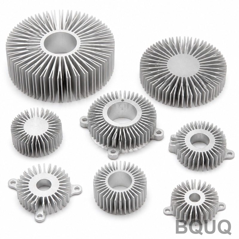
Heat Sink Design Checklist: From Watts to Production
Short answer: Start with the watts you must move and the space you have. A natural-convection aluminum extrusion typically handles 0.5–2 W per 10 mm of fin height per 100 mm of length, but the only number that matters is the required thermal resistance in °C/W. Divide allowable temperature rise by wattage, subtract interface and spreading losses, then design fins, base thickness and material around what is left. Confirm the profile can actually be extruded, machined or stamped, and lock the finish before tooling. BQUQ quotes custom heat sinks in 12 working hours from one ISO9001 factory in Dongguan.
Why does the wattage number lie to you?
Most heat sink projects start with a single figure: "we need to dissipate 40 W." That number is almost never the whole story. What matters is the continuous wattage, the peak wattage, the duty cycle, and how long the peak lasts.
A 40 W steady load and a 40 W pulse lasting 200 ms are completely different thermal problems. The first needs a heat sink sized for steady-state conduction. The second may be satisfied by thermal mass alone, with the heat sink acting as a buffer rather than a radiator.
Build a load profile, not a single number
Before any geometry work, write down:
- Continuous power (W) and peak power (W)
- Peak duration and duty cycle
- Ambient temperature range, including the worst-case inside an enclosure
- Maximum allowable component temperature (junction, case, or surface)
- Airflow available: none, fan-assisted, or forced duct
If you cannot fill in all five, you are designing blind. Most overheating failures trace back to an optimistic ambient assumption, not to a badly shaped fin.
Convert to required thermal resistance
The governing equation is simple:
R_total = (T_component_max − T_ambient) / P
If a device must stay below 95 °C in a 45 °C ambient while dissipating 30 W, the total thermal path must be under 1.67 °C/W. That budget is shared across junction-to-case, interface material, spreading through the base, and convection to air. A realistic split for a medium-power module might look like this:
| Path element | Typical share of budget | Notes |
|---|---|---|
| Junction to case | 20–35% | Fixed by the device package |
| Interface material | 5–15% | Depends on TIM and mounting pressure |
| Spreading in base | 10–20% | Grows with small source on large base |
| Convection to air | 40–60% | The part you actually design |
Notice that the heat sink itself rarely gets more than half the budget. Engineers who design the fins first and check the interface last usually end up re-tooling.
Which material should you choose?
Aluminum and copper dominate for good reasons. Aluminum is roughly one-third the density and a fraction of the cost; copper conducts heat about 1.7 times better but weighs three times as much and costs several times more per kilogram.
| Property | Aluminum 6063 | Copper C11000 | Practical implication |
|---|---|---|---|
| Thermal conductivity | ~200 W/m·K | ~390 W/m·K | Copper spreads heat faster |
| Density | ~2.7 g/cm³ | ~8.9 g/cm³ | Copper is heavy and costly |
| Extrudability | Excellent | Poor | Copper suits skiving, not extrusion |
| Relative material cost | 1× | 3–4× | Copper only where it earns its place |
| Typical use | Extrusions, die castings | Skived fins, cold plates, heat pipes | Hybrid designs are common |
When copper is justified
Copper earns its cost in three situations: very high heat flux from a small source, tight spreading budgets where the base must move heat laterally, and compact designs where fin area is limited. A copper base with aluminum fins — sometimes called a copper-base aluminum-fin heat sink — captures most of the spreading benefit at a fraction of the total cost. This is a common architecture in power electronics and high-brightness LED modules.
When aluminum wins outright
For anything above roughly 100 mm in footprint with moderate flux, an extruded aluminum heat sink is almost always the right answer. Extrusion gives you continuous fin profiles, low unit cost at volume, and excellent dimensional consistency. If your design is a natural-convection enclosure panel, extrusion is the default.
How do you size fins without guessing?
Fin geometry is a trade-off between surface area and airflow. More fins mean more area, but tighter spacing means thicker boundary layers and less air movement. There is an optimum, and it moves depending on whether you have a fan.
Fin spacing rules of thumb
| Cooling mode | Typical fin gap | Fin thickness | Notes |
|---|---|---|---|
| Natural convection | 8–12 mm | 1.5–3 mm | Wide gaps let buoyant air escape |
| Low-speed fan | 4–8 mm | 1–2 mm | Balance area against pressure drop |
| High-speed forced air | 1.5–4 mm | 0.6–1.5 mm | Dense fins need real static pressure |
| Liquid cold plate | 0.5–2 mm | 1–2 mm | Channel geometry driven by flow rate |
These are starting points, not laws. A natural-convection heat sink with 4 mm fin gaps will run noticeably hotter than the same profile at 10 mm, even though it has more surface area.
Fin efficiency and the point of diminishing returns
Fins only help if heat actually reaches the tip. Fin efficiency falls as fins get taller, thinner, and more conductive-limited. For aluminum fins in air, efficiency often drops below 70% once the fin exceeds roughly 25–30 mm in height with a 1.5 mm thickness. Beyond that, adding height adds material and cost without proportional performance.
Base thickness matters more than people expect
A thin base saves weight but chokes spreading. For a small die on a large base, base thickness of 5–10 mm is common in aluminum. If you are moving 200 W from a 20 mm × 20 mm source, spreading resistance in the base can easily be the second-largest term in the budget after convection.
What does the manufacturing route change?
The same thermal geometry can be produced several ways, and the choice affects cost, lead time, and achievable fin ratio.
Extrusion
Best for constant cross-section profiles at volume. Aluminum extrusion heat sink profiles can reach fin aspect ratios around 10:1 to 15:1 depending on alloy and wall thickness. Tooling is a one-time die cost; per-part cost drops sharply with quantity. Extrusion cannot produce cross-drilled holes, undercuts, or varying fin heights along the length without secondary machining.
Skiving
Skiving folds or shaves fins from a solid block, producing very dense, tall fins with excellent base-to-fin continuity. It suits copper and aluminum where extrusion cannot reach the required fin density. Tooling is lower than a die, but cycle time is higher.
Stamping and bonded assemblies
For low-profile or space-constrained designs, stamped aluminum heat sinks and bonded-fin assemblies let you mix materials and shapes. Bonded fins allow copper base with aluminum fins, or folded fins that pack high area into a shallow envelope.
Die casting and forging
Die-cast aluminum heat sinks handle complex 3D shapes, mounting bosses and enclosures in one part, but thermal conductivity is lower than wrought alloy and fin thickness must be generous. Forged heat sinks give better density and conductivity than castings but cost more in tooling.
CNC machining
CNC machining handles the base, mounting holes, pockets for heat pipes, flatness-critical interfaces and small-batch production. For custom heat sinks where the profile is not extrudable, or where quantities are in the hundreds, machining the whole part is often faster than waiting on a die. BQUQ machines heat sinks to ±0.005 mm where interface flatness matters.
Which finish and interface decisions bite later?
Surface finish and flatness
A machined base with a flatness of 0.05 mm and an Ra under 1.6 µm gives a predictable interface. Rough or warped bases force thicker thermal interface material, and every extra 0.1 mm of TIM adds resistance. If you are bonding or using a phase-change pad, specify flatness explicitly on the drawing.
Anodizing, plating and bare finishes
Black anodizing adds a few microns of emissivity benefit for natural convection and radiation, but it is a dielectric layer — do not rely on anodized surfaces for electrical grounding. Nickel plating is used where solderability or corrosion resistance matters. Bare mill finish is cheapest and often adequate in forced-air designs.
Mounting and fan integration
Screw torque, spring clips and fan mounting all affect contact pressure. A heat sink with fan mounting bosses designed in from the start avoids brackets and secondary hardware. Decide early whether the fan mounts to the heat sink or the enclosure.
How do you move from prototype to production?
Validate with a thermal spec sheet
Before committing to tooling, define the acceptance criteria: wattage, ambient, airflow, allowable case temperature, and the measured thermal resistance. A structured thermal spec sheet keeps the supplier and the design team aligned and prevents "it feels cooler" arguments.
Prototype in the real material
Prototypes machined from the production alloy behave differently from 3D-printed plastic or resin models. If you need fast iteration, machined prototypes in the final alloy give you real thermal data.
Design for the process you will actually use
The most common cost mistake is designing an extrudable-looking profile that then needs five machining operations. If the volume is 500 pieces, extrusion plus machining may still win. If it is 50 pieces, machine it. If it is 50,000, invest in the die and design for it.
Frequently Asked Questions
Q: What is the first number I need for heat sink design?
A: The required thermal resistance in °C/W, derived from allowable temperature rise divided by wattage. Everything else — fin geometry, material, base thickness — is a consequence of that number. Engineers who start with dimensions instead of watts usually iterate more and spend more. Write the thermal budget down before sketching anything.
Q: Is copper always better than aluminum for heat sinks?
A: No. Copper conducts roughly 1.7 times better but weighs about three times more and costs several times more per kilogram. It wins for high heat flux from small sources and tight spreading budgets. For large footprints with moderate flux, aluminum extrusion is cheaper, lighter and thermally adequate. Hybrid copper-base aluminum-fin designs often give the best balance.
Q: How much does fin spacing affect performance?
A: It can swing performance by 20–40% in natural convection. Fins spaced too tightly choke buoyant airflow and thicken boundary layers, so a denser heat sink can run hotter than a sparser one. Typical natural-convection gaps are 8–12 mm; forced-air designs can go to 1.5–4 mm because the fan supplies static pressure.
Q: Can you quote a custom heat sink without a full drawing?
A: Yes. A sketch with overall envelope, wattage, ambient, airflow and mounting constraints is enough to start. BQUQ returns a quote in 12 working hours and supports flexible MOQ, so early-stage projects can be priced before the design is frozen. Send files to sc@bquq.com or WhatsApp +86 13713157787.
Q: What causes most heat sink failures in the field?
A: Interface problems, not fin geometry. Warped bases, insufficient mounting pressure, dried-out thermal pads and optimistic ambient assumptions account for most overheating returns. Specifying base flatness, TIM thickness and mounting torque on the drawing prevents the majority of these issues before production begins.
Related Resources
- About BQUQ and our Dongguan factory: /about/
- Custom heat sinks and thermal hardware: /heat-sinks/
- Extruded aluminum heat sink profiles: /extruded-heat-sinks/
- CNC machined heat sinks and cold plates: /cnc-machined-heat-sinks/
- Industry trends in thermal management: /industry-dynamics/
- Technical articles and engineering guides: /bquq-blog/
- Frequently asked questions: /faq/
- Contact the engineering team: /contact/
Authored by the BQUQ Engineering Team. BQUQ (Dongguan) runs CNC machining (±0.005 mm), metal stamping, custom springs, and heat sink production in one ISO9001 factory. Source-direct from Dongguan, China — quote in 12 hours: sc@bquq.com | WhatsApp +86 13713157787 | www.bquq.com


