
BQUQ sizes natural convection heat sinks: area equation, fin spacing, black anodizing and orientation derates. Dongguan factory, quote in 12 hours.
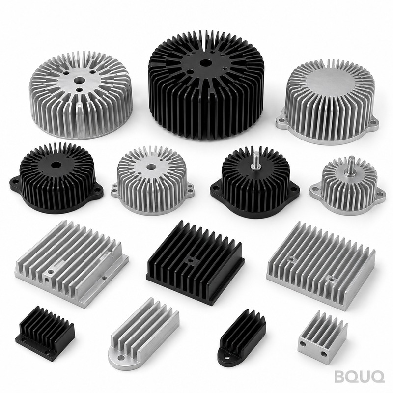
Sizing Heat Sinks for Natural Convection
Short answer: size a natural convection heat sink with A = P ÷ (h × ΔT), where h for a vertical finned sink is roughly 4–8 W/m²·K including radiation on a black anodized surface, and ΔT is the allowed sink-to-air rise. A 20 W LED driver allowing a 40 °C rise needs on the order of 600–900 cm² of finned surface; a 50 W load at the same rise needs roughly 1,500–2,000 cm² and a noticeably large extrusion. Space vertical fins 6–12 mm apart, keep the sink vertical with fins vertical, and expect roughly 20–40% derating if the fins sit horizontal or the air path is blocked. If the calculated footprint looks too big, natural convection is the wrong answer — that is the signal to add airflow.
Natural convection is the quiet end of thermal design: no fan, no noise, no moving parts to fail, and no dust loading on a filter. It is the default for LED luminaires, power adapters, instrumentation, and any product where reliability and silence outrank raw cooling. The cost is size. Air moving by buoyancy alone is a weak heat carrier, so the sink must present a large surface in a geometry that lets warm air rise away cleanly. Sizing is not a mystery — it is one equation, one set of fin-spacing rules, and an honest check on whether the answer fits your product.
The Sizing Equation and the Real Value of h
The steady-state balance for a sink cooling in still air is the same as any convection problem: heat out equals the effective surface coefficient times the wetted area times the temperature rise, P = h × A × ΔT. Rearranged, the surface area you need is A = P ÷ (h × ΔT). The art is in h, the effective coefficient, because natural convection h is small and radiation contributes a large share of it.
For a vertical plate or a sink with vertical fins, the pure convection coefficient runs roughly 3–6 W/m²·K depending on size and temperature rise. Radiation adds roughly another 2–4 W/m²·K of equivalent coefficient when the surface is black anodized, because the coating lifts emissivity from about 0.1 on bare aluminum to about 0.85–0.95. That is why the practical planning number for a black anodized vertical finned sink is about 6–9 W/m²·K, and why bare polished aluminum underperforms dramatically in passive designs — you lose radiation, which can be a third of the total heat path. Every radiator and heat sink in passive service should be anodized black unless the application forbids the color.
A Worked Sizing Example You Can Copy
Size a sink for 20 W from an LED driver, case target 80 °C at 40 °C ambient, giving ΔT = 40 °C. Assume a black anodized sink with vertical fins and h = 7 W/m²·K. Required area A = 20 ÷ (7 × 40) = 0.071 m², about 710 cm² of finned surface. A 150 × 150 mm footprint with 15 mm tall fins on both sides delivers roughly that area; the exact fin count comes from the spacing rules below. If the product allows only a 20 °C rise — for example a plastic enclosure nearby that cannot tolerate heat — the area doubles to about 1,400 cm², which shows why the temperature budget is the single biggest lever in passive design.
| Heat load | ΔT allowed | h used | Required finned area | Typical sink class |
|---|---|---|---|---|
| 10 W | 40 °C | 7 W/m²·K | ~360 cm² | 100 × 100 mm base, 15–20 mm fins |
| 20 W | 40 °C | 7 W/m²·K | ~710 cm² | 150 × 150 mm base, 15–20 mm fins |
| 20 W | 20 °C | 7 W/m²·K | ~1,430 cm² | Large extrusion, tall fins |
| 50 W | 40 °C | 7 W/m²·K | ~1,790 cm² | 200 × 200 mm class or fanless chassis |
| 50 W | 40 °C | 4 W/m²·K (bare Al) | ~3,130 cm² | Impractical — anodize, or add airflow |
The table is deliberately simple: real designs multiply in fin efficiency, which for widely spaced short fins is near 90% and for tall dense fins falls well below, and they account for the heat source footprint spreading. The numbers are area targets, and the fin efficiency and packing rules that turn area into real fins are covered in the fin design guide. What the table communicates is scale: passive cooling is generous with space, and radiation plus anodizing is worth roughly 40–75% more effective area than the same sink bare.
Fin Spacing: The Rule That Most Designs Get Wrong
Fins in natural convection create their own airflow: each channel of air between fins heats up and rises, drawing cool air in from below. If fins are too close, the boundary layers from each fin merge, the air stops flowing, and the inner fins do almost nothing — the sink gains surface area that never touches moving air. If fins are too far apart, the air flows freely but you wasted base area and weight. The practical spacing band for passive sinks is a gap of roughly 6–12 mm, wider for taller fins because the rising column needs more room to accelerate.
| Fin height | Recommended fin gap (natural convection) | Typical fin count per 25 mm |
|---|---|---|
| 10–15 mm | 5–8 mm | 3–4 |
| 15–30 mm | 6–10 mm | 3 |
| 30–60 mm | 8–12 mm | 2–3 |
| Horizontal fins | 10–15 mm + derate | 2–3 |
Compare those gaps with forced-air sinks, where gaps of 1.5–3 mm are common because the fan pushes air through tight channels. Trying to force-convection-optimize a passive sink, or vice versa, is the most common rookie error in heat sink selection — the full comparison of the two regimes lives in the natural vs forced convection guide. For passive designs, fewer, taller, well-spaced fins beat many thin fins every time.
Orientation, Blockage and the Derates You Must Apply
Natural convection is gravity-driven, so orientation is not cosmetic — it is worth 20–40% of performance. Best case is the sink mounted vertically with fins vertical, so heated air rises straight up through the channels and pulls cool air from below. Mount the same sink with fins horizontal and the air must turn corners at each channel, cutting capacity by roughly 15–30%. Lay the whole assembly face-up under a flat cover and airflow stops entirely, leaving only radiation and conduction to the enclosure. If your product orientation varies, size for the worst case, because a passive sink that is undersized in its intended orientation will fail in the field with no fan to compensate.
Blockage matters almost as much as orientation. A sink needs clearance below and above for the air to enter and leave: typically 10–20 mm of open space under the fins and unobstructed exit above. Enclosure walls close to the fin tips choke the flow, and a sealed enclosure defeats passive cooling entirely — the heat still has to leave the box, so passive designs usually need vent openings or a metal chassis as the final radiator. When you cannot give the air a path, the honest options are forced convection or moving heat to the enclosure wall, not a bigger sink.
Frequently Asked Questions
Q: What is the best fin spacing for a natural convection heat sink?
A: A gap of roughly 6–12 mm between fins, wider for taller fins, is the practical band for passive cooling. Gaps below 5 mm choke the buoyant airflow and add surface area that does not work, unlike forced-air sinks where tight gaps are normal.
Q: How do I calculate the surface area my passive heat sink needs?
A: Use A = P ÷ (h × ΔT) with h around 6–9 W/m²·K for a black anodized vertical finned sink, and ΔT the allowed sink-to-air rise. A 20 W load at 40 °C rise needs roughly 600–900 cm² of finned area, and every degree of allowed rise you save shrinks the sink proportionally.
Q: Does black anodizing really improve natural convection performance?
A: Yes, significantly. Bare aluminum has an emissivity of about 0.1, while black anodized aluminum reaches about 0.85–0.95, and radiation can carry roughly a third of the heat in passive service. The same sink anodized black behaves like a sink with 40–75% more effective area.
Q: How much does mounting orientation affect a passive heat sink?
A: Typically 15–30% between vertical fins and horizontal fins, and much more if airflow is blocked. Natural convection depends on warm air rising through the fin channels, so mount fins vertical, leave 10–20 mm clearance below for intake air, and keep the exit above unobstructed.
Q: When should I stop trying to make natural convection work?
A: When the required surface area or footprint stops fitting your product, or when the enclosure is sealed. Passive cooling is generous with space by nature, and if the calculation returns an impractical sink, adding a fan or moving heat to the enclosure wall is cheaper than forcing a giant extrusion.
Related Resources
- Natural vs forced convection heat sinks — when to cross from passive to active cooling.
- Heat sink sizing calculation — the full step-by-step method with resistance budgets.
- About BQUQ: an ISO9001 source factory in Dongguan machining, cutting and anodizing heat sinks under one roof.
- Contact us: send your watts, ambient and size limits for a design review within 12 working hours.
Authored by the BQUQ Engineering Team. BQUQ is an ISO9001-certified source factory in Dongguan, China, running CNC machining, metal stamping, custom springs, heat sink and collet lines under one roof. Send drawings to sc@bquq.com or WhatsApp +86 13713157787 for a quote within 12 working hours. www.bquq.com


