
Fin spacing, height and orientation with typical values for passive and fan-cooled heat sinks. BQUQ (ISO9001, Dongguan) quotes in 12 hours.
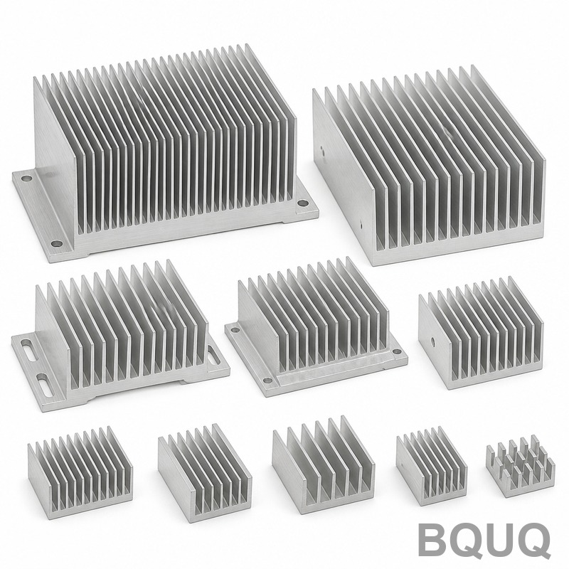
Heat Sink Fin Design: Spacing, Height and Orientation That Actually Work
Fin spacing, height, and orientation decide whether a heat sink performs or just looks like one. For natural convection, keep vertical fins on roughly 7-11 mm pitch (6-10 mm open gap) and 25-50 mm tall; for forced air you can close the gap to 2-4 mm and carry roughly double the fin area in the same footprint. Fix spacing first, then height, then orientation — most bad heat sink designs die on spacing alone.
Air is the working fluid, and fin geometry exists for one reason: to put as much metal surface in contact with moving air as possible. Once the airflow stops reaching a fin, that fin is dead weight that adds mass and cost but no cooling. This guide gives you the numbers that actually work for extruded and machined aluminum sinks, and the manufacturing limits that will bite you if you ignore them.
Fin Spacing for Natural Convection: Wide Beats Dense
In free air, the boundary layer that forms on each fin surface thickens as it travels upward. If gaps are too narrow, boundary layers from adjacent fins meet, flow chokes, and the inner fin area goes stagnant. If gaps are too wide, you waste envelope on empty space that could carry another fin.
The practical working band for vertical-plate natural convection sinks in electronics is a 6-10 mm open gap, which on typical 1.5-2.5 mm fins means roughly 8-12 mm pitch. The exact optimum shifts with temperature rise: hotter fins (larger delta-T) drive stronger buoyancy and tolerate slightly wider gaps.
| Natural convection design | Typical range | Notes |
|---|---|---|
| Fin-to-fin gap | 6-10 mm | Below ~5 mm flow chokes |
| Fin pitch (center to center) | 8-12 mm | Gap + fin thickness |
| Fin height | 25-60 mm | Beyond this, added height cools little |
| Fin thickness | 1.5-3 mm | Extrusion-friendly range |
| Delta-T fin vs ambient | 40-80 K | Drives buoyancy and optimum gap |
Takeaway: if you are designing a passive sink and the pitch is under ~6 mm, you are building a dust trap with a fan-shaped problem — the flow simply will not go where you need it. Recheck the numbers against your heat sink thermal resistance calculation before committing to a profile.
Forced Air: Dense Fins, but Watch Pressure Drop
Add a fan and the rules invert. Moving air defeats boundary-layer growth, so gaps can shrink to 2-4 mm and fin counts climb. The price is pressure drop: every extra fin and every millimeter of length adds flow resistance, and a weak axial fan stalls against a dense array even though its datasheet says it moves air.
| Air velocity over fins | Typical convective coefficient | Practical min gap |
|---|---|---|
| Natural (0 m/s) | 3-10 W/m²·K | 6-10 mm |
| 1-2 m/s | 15-40 W/m²·K | 3-5 mm |
| 3-5 m/s | 40-90 W/m²·K | 2-3.5 mm |
| Ducted high pressure | 90-250 W/m²·K | 1.5-2.5 mm (bonded/skived) |
Takeaway: pick gap from the velocity your fan actually delivers at the fins, not its free-air spec. A 5 mm gap at 2 m/s usually outperforms a 2 mm gap at the same fan because the air actually arrives. Compact, high-density arrays are only worth it with a blower or ducted high-static-pressure fan.
Fin Height: Where Efficiency Collapses
Tall fins add surface, but each additional millimeter works less than the one before it. Heat conducts up a fin while losing energy out both sides, so the temperature profile decays along the height. Fin efficiency at typical natural-convection coefficients stays above 90% for short fins and slides steadily as fins grow.
| Fin height (1.5 mm thick, aluminum) | Typical fin efficiency |
|---|---|
| 10 mm | ~97-99% |
| 25 mm | ~93-96% |
| 50 mm | ~85-92% |
| 100 mm | ~65-80% |
Takeaway: beyond roughly 40-60 mm in natural convection and 60-80 mm in modest forced air, added height buys far less than added base area or a second sink. If your envelope forces tall fins, that is the moment to compare extruded heat sinks against CNC-machined heat sinks with thicker, shaped fins.
Fin Thickness and Aspect Ratio: Extrusion Physics
Fins do not come out of the die infinitely thin and tall. Extruded aluminum profiles have real limits: minimum fin thickness around 1-1.3 mm for 6063-T5, and an economical height-to-gap aspect ratio near 6-8 to 1. Push beyond that and the die becomes fragile, the profile runs slow, and cost climbs disproportionately.
If your design demands thin tall fins, the manufacturing route changes. Skived and bonded fin sinks reach much higher density, and CNC machining lets you cut thicker fins, undercut channels, or stepped heights that no die can produce. Each process has its own geometry envelope, so the heat sink types guide is worth reading before you finalize a fin cross-section.
| Fin requirement | Extruded | CNC machined | Bonded/skived |
|---|---|---|---|
| Min fin thickness | ~1.0-1.3 mm | ~0.8 mm (cut from solid) | ~0.3-0.5 mm |
| Max practical height | ~100-150 mm | limited by blank size | 100 mm+ |
| Height-to-gap ratio | ~8:1 economical | ~12:1 | ~20:1 |
| Tooling cost | Extrusion die | None (programming) | Die + bond/fixture |
Takeaway: extrusion is the cheapest route at volume but has the tightest geometry cage; if your thermal analysis demands a fin aspect ratio past about 8:1, budget for a non-extrusion process instead of forcing the die.
Orientation: Vertical Wins in Free Air
Natural convection depends on the chimney effect. Fins should stand vertical with the channel open at top and bottom so heated air rises and pulls cool air in behind it. Turn that same sink so fins run horizontal and free-convection performance drops by roughly 20-30% because buoyant air cannot establish a clean vertical channel.
Forced-air orientation is more forgiving but still directional: aim the flow down the fin channels, not across them. A shrouded duct that forces all fan air through the channels is worth 10-25% over an unshrouded fan blowing at a fin block from the side.
Two practical rules from the shop floor: never trap the hot side of a passive sink against an enclosure wall, and leave at least one full fin pitch of clearance below and above a vertical array so air can enter and exit. Customers regularly lose half their cooling by mounting a fine sink flat under a sealed lid.
Checklist to Send Your Factory
A fin geometry is only as good as the drawing that defines it. When you request heat sink quotes, include: dissipated watts and max allowable case temperature, ambient range and whether the sink is ducted, airflow or fan model if forced, envelope dimensions, fin pitch/height/thickness, mounting hole pattern and base flatness needs, and the alloy — 6063-T5 if thermal performance leads, 6061-T6 if the base carries structural load. Missing airflow assumptions are the number one cause of a quoted sink that does not cool: the factory sizes the profile, but only you know the real air velocity at the fins. Send watts, temperatures, and airflow together and the geometry practically designs itself.
Email sc@bquq.com or WhatsApp +86 137 1315 7787 with your PDF/DXF/STEP file. An engineer reviews it and replies with price, lead time and DFM notes on working days.
Frequently Asked Questions
Q: What fin spacing should I use for a natural convection heat sink?
A: Roughly 6-10 mm open gap between fins, which lands most designs at 8-12 mm pitch with 1.5-3 mm fins. Below about 5 mm, natural convection chokes because boundary layers merge and the inner fin area goes stagnant.
Q: When does a heat sink need forced air instead of bigger fins?
A: When the required surface area cannot fit your envelope or fin efficiency collapses — typically past roughly 0.05-0.1 m² of exposed area for a passive design in a compact case. A slow 1-2 m/s airflow more than doubles the convective coefficient, so a small fan usually beats a giant fin block.
Q: What is the maximum fin height-to-gap ratio for extruded aluminum heat sinks?
A: Economical extrusion stays near 6-8 to 1 height-to-gap with minimum fin thickness around 1-1.3 mm. Beyond that, die life and extrusion speed suffer; bonded, skived, or CNC-machined fin construction becomes the sensible route.
Q: Do vertical fins always outperform horizontal fins?
A: In natural convection, yes — vertical channels create the chimney draft that drives airflow, and horizontal fins typically cost 20-30% performance. Under a fan the penalty shrinks, but flow should still travel down the channels rather than across them.
Q: How do I choose between 6063 and 6061 for finned heat sinks?
A: Use 6063-T5 for the fins themselves because it conducts around 200 W/m·K, measurably better than 6061-T6 at roughly 155-170 W/m·K. Pick 6061 only when the base doubles as a structural member that needs higher yield strength.
Related Articles
- led-heat-sink-selection-guide — More from the BQUQ Thermal Management engineering series.
- air-cooling-vs-liquid-cooling-electronics — More from the BQUQ Thermal Management engineering series.
- heat-sink-mounting-methods-guide — More from the BQUQ Thermal Management engineering series.
Data Sources and Verification
Tolerances, cycle times and price ranges in this guide come from BQUQ production records at our Dongguan plant, where CNC machining (±0.005 mm), stamping, custom springs and heat sinks run under one roof. BQUQ is an ISO 9001:2015 certified factory; the certificate and batch inspection reports are available on request with every quotation.
Related Resources
- About BQUQ: an ISO9001-certified source factory in Dongguan running four production lines under one roof.
- Heat sinks and thermal parts: extruded, CNC-machined and stamped options from the thermal line — extruded heat sinks, CNC-machined heat sinks, stamped heat sinks.
- Industry trends: manufacturing, material market, and sourcing analysis for buyers.
- Technical articles: engineering guides and process comparisons — more where this article came from.
- FAQ hub: quick answers on CNC, stamping, springs, and heat sinks.
- Case studies: real parts and real numbers from projects we engineered and delivered.
- Contact us: send your drawing and get a quote within 12 working hours.
Authored by the BQUQ Engineering Team. BQUQ is an ISO9001-certified source factory in Dongguan, China, running CNC machining, metal stamping, custom springs and heat sink lines under one roof. Send drawings to sc@bquq.com or WhatsApp +86 13713157787 for a quote within 12 working hours. www.bquq.com


