
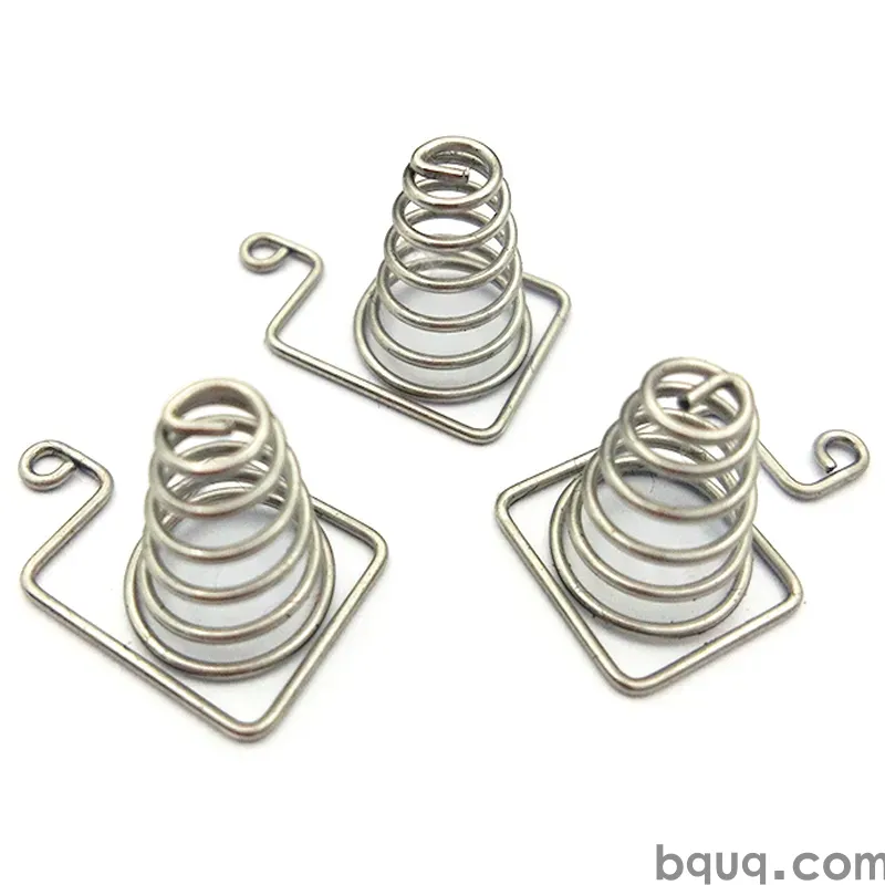
Stamped Parts for Cable Shielding and Grounding
Short answer: a cable shield only works if its ground path is short, wide and low-resistance. Stamped parts — clamps, ferrule rings, grounding clips and shield cans — are the usual way to capture that path, holding ±0.05 mm on mating features, from 0.15–0.60 mm strip, in brass, phosphor bronze, copper or stainless. Tin at 2–5 µm gives solderability; nickel or gold keeps resistance low at the contact point. The design rule is simple: bond the shield to chassis over the shortest possible loop, using as much metal as the space allows.
Every shielded cable has two parts to the grounding problem. The first is capturing the braid or foil so current can leave the shield. The second is carrying that current to chassis with low impedance across the frequency band of interest. Stamped parts do both jobs cheaply and can be tailored to the cable, the connector and the mounting.
What the Parts Have to Do
A grounding or shielding part has one electrical job and one mechanical job. Electrically, it must present a low, stable impedance from the shield to chassis — low resistance at DC, and low inductance at high frequency. Inductance is why a short, wide, flat strap beats a long, thin pigtail: the pigtail's length adds impedance that ruins shielding at radio frequencies even when its DC resistance looks fine.
Mechanically, the part must survive the cable's service life. It has to grip the braid without cutting it, resist vibration, and either solder, crimp or press onto the chassis reliably. That is where stamping shines: a formed ring can wrap the braid, a clip can snap onto a chassis edge, and a tab can be soldered or screw-mounted, all from one strip layout.
Types of Stamped Grounding and Shielding Parts
The family is wider than most buyers expect. Cable clamps and P-clips hold bundles and can double as ground straps when bonded. Ferrule rings and crimp sleeves capture braid around a connector shell. Grounding clips and fingers spring against a chassis or a shield can, providing the contact that closes the loop. EMI shield cans enclose a module. Eyelets and grommets line a pass-through hole and can carry a ground connection where the cable passes a wall.
Each type has a preferred material. Clamps that must not relax use spring alloys; shield cans that must solder use tin-plated brass or stainless; high-current ground straps use copper, often with a spot of silver where the contact presses.
Design Rules for a Low-Impedance Ground Path
| Parameter | Target | Why |
|---|---|---|
| Loop length | as short as possible | Inductance scales with length |
| Strap width | as wide as space allows | Lowers inductance |
| Contact force | 1–5 N typical | Stable contact without cutting |
| Contact resistance | <10 mΩ per point | Keeps voltage drop low |
| Plating at contact | tin, nickel or gold | Prevents oxide build-up |
| Bond point count | 2+ where possible | Redundancy under vibration |
The width rule is the one buyers most often miss. Two narrow contacts in parallel are not the same as one wide contact, because the current crowds into the same small region. Where a cable shield must be grounded well, spread the contact over a wide area and use more than one point. Where the part is only mechanical, force and corrosion dominate instead, and the electrical numbers can relax.
Materials and Plating for Cable Grounding Parts
| Material | Strip thickness | Plating | Use |
|---|---|---|---|
| C2680 brass | 0.20–0.50 mm | Tin 2–5 µm | Clamps, rings, solderable tabs |
| C5210 phosphor bronze | 0.15–0.40 mm | Tin or Ni | Spring clips, fingers |
| C110 copper | 0.20–0.60 mm | Tin, spot silver | High-current straps |
| SUS 301 stainless | 0.15–0.30 mm | Ni 1–3 µm or bare | Corrosion-resistant clips |
Tin is the common choice because it is cheap, solderable and reasonably stable. Where the contact mates and unmates, nickel or a gold flash keeps resistance low through cycles. Where the part sits outdoors, stainless or a plated steel survives better than bare copper. The plating choice at the contact point matters more than plating elsewhere on the part, so spot plating is normal.
Termination Methods and Their Trade-offs
Crimp, solder, press-fit and screw each suit a different situation. Crimping is fast and repeatable and suits a factory assembly; it needs a controlled crimp height and a pull-force check. Soldering gives the lowest resistance but requires heat control and a solderable finish, and a cold joint looks fine until it fails. Press-fit avoids both heat and solder but needs a tight tolerance and a controlled hole. Screw mounting is repairable but adds a fastener and a loosening risk under vibration.
For a stamped clip that must both grip and ground, the usual answer is a formed spring finger with a defined force and a plated contact zone. That is the same design logic as a stamped EMI contact, where contact force and wipe are tuned so the contact stays clean and stable. When the part is a grounding clip specifically, the grounding clips design guide covers force and retention in more depth.
Testing and Quality for Shielding Parts
A grounding part is verified by measurement, not by appearance. The key tests are contact resistance (often milliohms), pull or peel force for crimps and clips, and where shielding matters, transfer impedance or shielding effectiveness on a sample assembly. For tin-plated contacts, a simple check is a low-resistance measurement before and after a vibration or thermal cycle, since oxide growth and relaxation are the failure modes that matter.
Inspection should include the contact force and the resistance-critical dimensions: the grip height of a clamp, the finger height of a clip, the inner diameter of a ferrule ring. Tolerance on these is typically ±0.05 mm. Where the part is also a spring, the load at a given deflection is the functional check, measured on a sample. A first-article report should carry those numbers so the production parts can be compared to them.
Sourcing Stamped Grounding Parts
Send the cable or connector it must fit, the sheet metal it must bond to, the current and frequency range, and the environment. That tells the factory the material, the force and the plating. Include the termination method and any testing target, and note whether the part must be solderable at the contact point. With that, a quote and a tooling estimate can be produced in 12 working hours, and a sample checked for force and resistance before production. For telecom-style grounding and shielding parts, see the wider set of connector stamping for telecom.
Frequently Asked Questions
Q: What material is best for a stamped cable grounding clip?
A: C5210 phosphor bronze at 0.15–0.40 mm for a spring clip, or C2680 brass if it is a rigid clamp. Tin plating at 2–5 µm suits solderable contacts; nickel or gold keeps resistance stable at a mating face.
Q: Why does a short ground strap work better than a long pigtail?
A: Inductance scales with length, so a long pigtail has high impedance at radio frequencies even when its DC resistance is low. A short, wide, flat strap keeps the shield-to-chassis loop small and effective.
Q: How tight should the tolerance be on a cable ferrule ring?
A: Critical grip dimensions are typically held to ±0.05 mm so the ring grips the braid without cutting it. Tighter calls are possible but usually unnecessary unless a specific pull force must be met.
Q: Tin or gold plating for grounding contacts?
A: Tin for cost and solderability on a fixed joint. Gold or nickel where the contact mates and unmates, or where contact resistance must stay low through many cycles or a corrosive environment.
Q: How do you test a stamped grounding part?
A: Contact resistance in milliohms, pull or peel force for the crimp or clip, and shielding effectiveness on a sample assembly where relevant. We ship a first-article report with those numbers on request.
Related Resources
- EMI shielding contacts guide: how contact force and wipe keep shields grounded.
- Stamped grounding clips: design rules for retention and low-resistance contact.
- Metal stamping services: stamped clamps, rings, clips and shield cans built on progressive dies.
- Contact us: send your drawing and get a quote within 12 working hours.
Authored by the BQUQ Engineering Team. BQUQ is an ISO9001-certified source factory in Dongguan, China, running CNC machining, metal stamping, custom springs, heat sink and collet lines under one roof. Send drawings to sc@bquq.com or WhatsApp +86 13713157787 for a quote within 12 working hours. www.bquq.com


