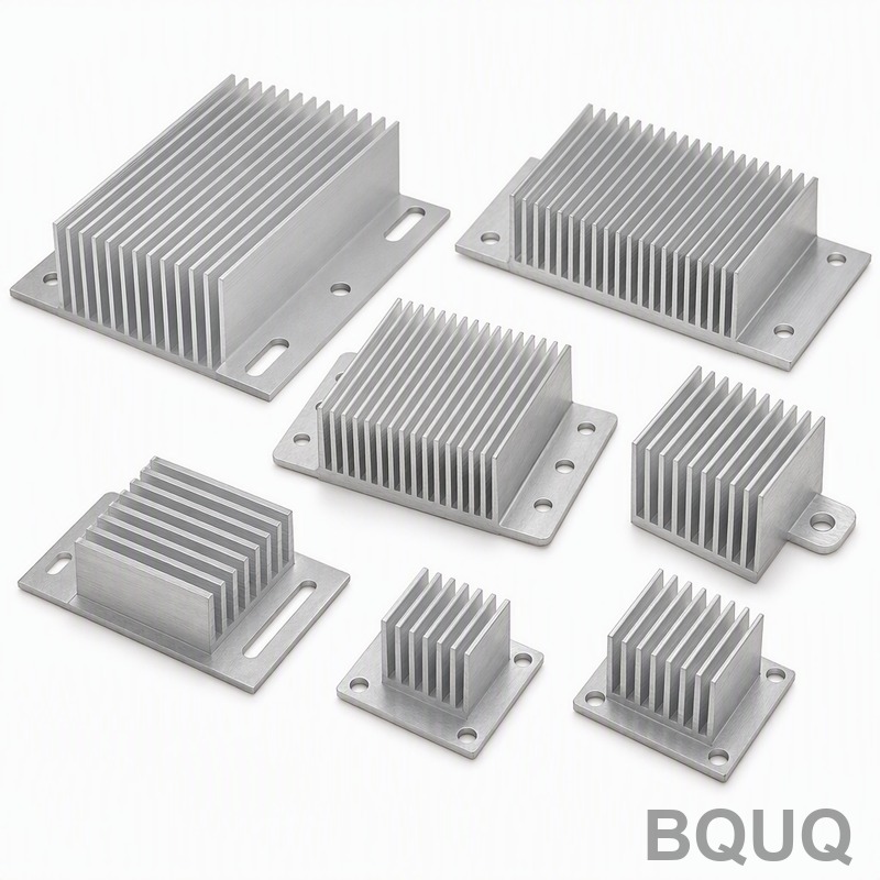
This is a CNC machined Mosfet Heatsink built for high-current switching applications where thermal runaway is a real risk. You get a flat mounting surface within 0.02 mm TIR, a ha
BQUQ CNC Machined Mosfet Heatsink – Precision Made in China
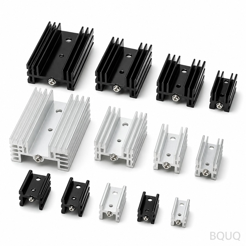
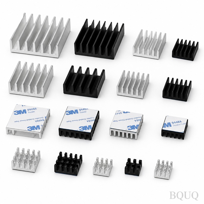
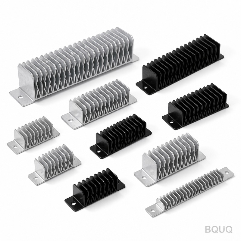
This is a CNC machined Mosfet Heatsink built for high-current switching applications where thermal runaway is a real risk. You get a flat mounting surface within 0.02 mm TIR, a hardness of 45 HRC on
Get a Fast Quote for This Part
Send us your drawing / quantity / material — reply within 24h.
This is a CNC machined Mosfet Heatsink built for high-current switching applications where thermal runaway is a real risk. You get a flat mounting surface within 0.02 mm TIR, a hardness of 45 HRC on the anodized surface, and a guaranteed lead time of 7 working days for standard profiles. We make these in Dongguan, China, with 20 years of precision manufacturing experience behind every fin.
Why Flatness Below 0.02 mm TIR Matters for Your Mosfet Junction
A Mosfet’s thermal resistance depends on the contact area between the device tab and the heatsink. If the surface is bowed or has high spots, the air gap traps heat and the junction temperature climbs past 125°C. We machine the base pad on a 5-axis CNC with a final fly-cut pass. This delivers a surface flatness of 0.02 mm TIR across the entire base, not just the center. You can mount a TO-247 or TO-220 package directly without lapping or thermal paste compensation.
Aluminum 6061-T6 vs. Copper C1100 – Material Options That Change Thermal Performance
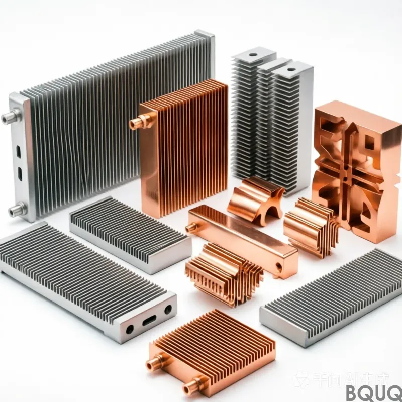
We stock two primary materials for Mosfet Heatsinks. Aluminum 6061-T6 is the default choice: 180 W/m·K thermal conductivity, 45 HRC hardness after hard anodizing, and a weight that keeps your PCB assembly manageable. For high-density SiC or GaN Mosfets that dissipate over 50 W per device, we recommend C1100 copper. It gives you 390 W/m·K conductivity but requires a nickel-plating step to prevent oxidation. We machine both with the same ±0.01 mm tolerance, and we can switch materials on the same drawing without changing your mounting hole pattern.
Fin Geometry That We Machine, Not Extrude – Aspect Ratios Up to 20:1
Extruded heatsinks force you into fixed fin thickness and spacing. We machine each fin individually. That means you can spec a 0.8 mm thick fin with a 4 mm gap, or a 1.5 mm fin with a 10 mm gap, on the same part. Our CNC mills handle fin heights up to 80 mm with an aspect ratio of 20:1 without vibration marks. The surface finish inside the fin channels is Ra 1.6 µm, which minimizes boundary layer resistance when you use forced air cooling. For natural convection, we can add a knurled texture on the fin tops to increase surface area by 15%.
Hard Anodizing to 45 HRC – Preventing Screw Stripping and Corrosion
A bare aluminum heatsink is soft. A #4-40 screw torqued to 5 in-lbs will strip threads after three installations. We apply a Type III hard anodize coating that penetrates 0.05 mm into the surface and measures 45 HRC. This protects the threaded holes you use to secure the Mosfet. The coating also gives you a dielectric breakdown voltage of 800 VDC, so you can mount a live tab directly without an insulator pad in low-voltage circuits. If your application requires solderability, we mask the anodize off the base pad and apply a bright tin finish instead.
Inspection Report with Every Mosfet Heatsink – CMM and Thermal Resistance Data
We measure every heatsink before it ships. A coordinate measuring machine (CMM) checks the base flatness, hole positions, and fin parallelism against your PDF drawing. We also run a thermal resistance test on a sample from each batch: we mount a 25 W resistor on the base, measure the case temperature rise, and record the result in °C/W. The full inspection report is emailed to you with the shipping documents. If you need PPAP Level 3, we generate that documentation at no extra cost for orders over 200 pieces.
Lead Time and Tooling – 7 Days for Standard, 15 Days for Custom Fin Patterns
Our standard Mosfet Heatsink profiles are machined from bar stock that we keep in-house. You get a 7-day lead time from drawing approval to shipment. For a custom fin pattern with a unique width or hole layout, the lead time is 15 days because we program a new tool path and cut a fixture. We do not charge for tooling on the first order. The MOQ is zero – we ship one prototype or ten thousand pieces at the same price per unit, because the CNC cycle time is the same.
Specification
Value
Material
Aluminum 6061-T6 or C1100 Copper
Base Flatness (TIR)
0.02 mm
Machining Tolerance
±0.01 mm
Surface Finish (Fin Channel)
Ra 1.6 µm
Surface Hardness (Hard Anodized)
45 HRC
Fin Thickness (Min)
0.8 mm
Fin Height (Max)
80 mm
Max Base Size
300 mm x 200 mm
Coating Options
Type III Hard Anodize, Bright Tin, Nickel
Standard Lead Time
7 Working Days
Custom Lead Time
15 Working Days
MOQ
No MOQ
Mounting Holes and Thread Inserts – We Machine Them, Not You
Stop drilling your own holes. We machine the mounting pattern for TO-220, TO-247, and TO-264 packages directly into the base. The hole depth tolerance is ±0.05 mm, and we tap threads in the same setup to ensure perpendicularity. If you use self-tapping screws, we can add a pilot hole with a chamfer that guides the screw without galling. For high-vibration environments, we press in brass or stainless steel threaded inserts that handle 30 re-torque cycles without wear.
What is the minimum order quantity for a custom Mosfet Heatsink?
There is no MOQ – we machine a single piece for prototyping or a full production run at the same per-unit cost because our CNC setup time is fixed.
Can you match an existing extruded heatsink design?
Yes, send us the part or a drawing and we will machine a drop-in replacement with tighter tolerances and optional hard anodizing that the original extruder cannot offer.
How do you verify thermal performance before shipping?
We mount a calibrated 25 W resistor on a sample heatsink, measure the case temperature rise in a 25°C ambient, and include the measured °C/W value in the inspection report.
What is the fastest lead time for a prototype?
If you approve a standard profile from our catalog, we can ship one piece in 3 working days using 24-hour machining and overnight air freight.
How to Send Your Drawing and Get a Firm Quote in 12 Hours
Send your step, IGES, or PDF drawing to sc@bquq.com. Include the Mosfet package type (TO-220, TO-247, etc.), the target case temperature, and the airflow you have available. We will reply within 12 hours with a firm price, a lead time, and a recommended material if you are unsure. For urgent requests, message us on WhatsApp at +86 13713157787 and we will review your drawing on the phone.