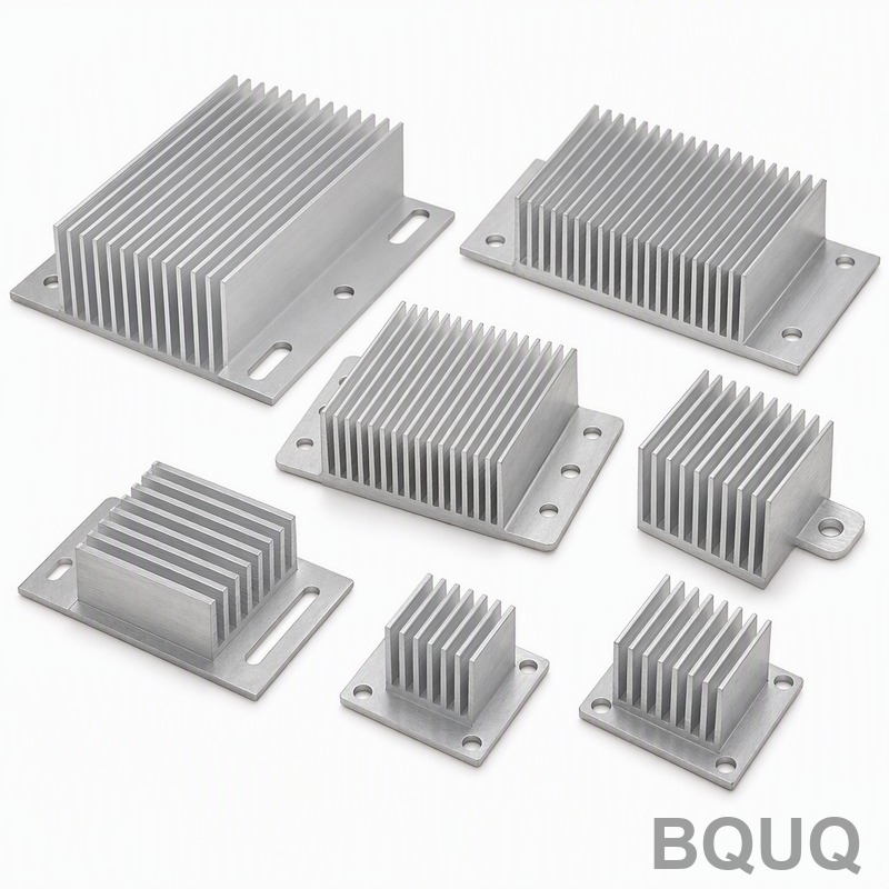
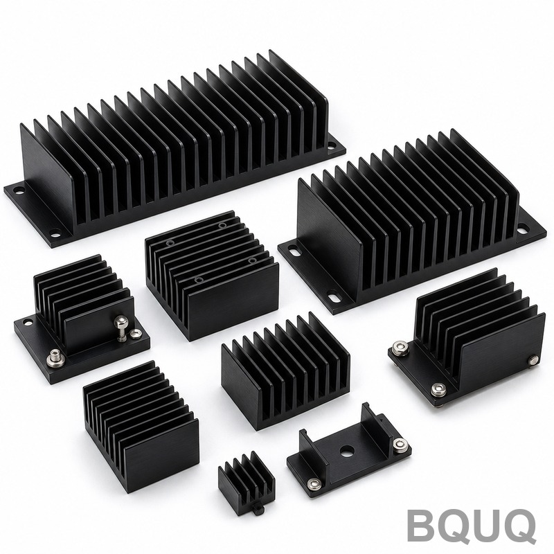
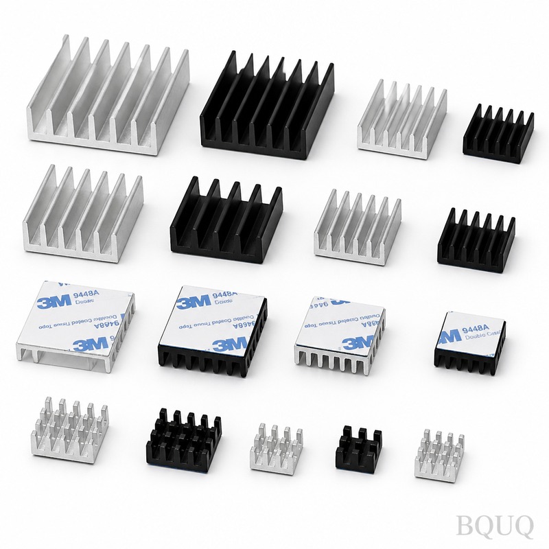
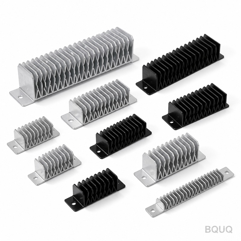
This is a collection of CNC-machined aluminum heatsinks with an integrated mounting base, designed for engineers who need a flat, stable thermal interface without secondary assemb
BQUQ Aluminum Heatsink With Mounting Base Collection | Precision Manufacturing
This is a collection of CNC-machined aluminum heatsinks with an integrated mounting base, designed for engineers who need a flat, stable thermal interface without secondary assembly. We hold base fla
Get a Fast Quote for This Part
Send us your drawing / quantity / material — reply within 24h.
This is a collection of CNC-machined aluminum heatsinks with an integrated mounting base, designed for engineers who need a flat, stable thermal interface without secondary assembly. We hold base flatness to 0.05 mm across the entire contact area, and all mounting holes are drilled to ±0.01 mm positional tolerance. Every unit ships from our Dongguan factory in 10 days, and we offer a no MOQ policy so you can prototype or ramp production at your own pace.
Why a Mounting Base Eliminates Thermal Interface Failure
Most extruded heatsinks rock on uneven PCB surfaces, creating air gaps that ruin thermal conductivity. Our mounting base is machined in the same setup as the fin array, which guarantees the base and fins are perfectly perpendicular. This single-piece construction removes the need for thermal tape or clamping frames in most applications. You get a consistent 0.02 mm surface profile across the base, which means your thermal pad or paste performs exactly as its datasheet promises.
Materials and Heat Treatment We Use
We stock 6063-T5 and 6061-T6 aluminum alloys, both with a minimum hardness of 80 HRC on the Brinell scale for 6063 and 95 HRC for 6061. For high-vibration environments, we offer a hard anodizing option that increases surface hardness to 300 HV and adds a dielectric breakdown voltage of 800 VDC. Raw material certificates are included with every order, and we can trace the melt batch to the foundry.
Machining Tolerances That Match Your Thermal Model
Your simulation assumes a specific contact pressure and flatness. We deliver on that assumption. Base thickness tolerance is ±0.05 mm, fin spacing is held to ±0.1 mm, and the mating surface is machined to Ra 0.8 µm. If your design uses a heat pipe or vapor chamber, we can machine a pocket with a depth tolerance of ±0.02 mm to ensure full contact. For a deeper look at how we control these variables, read our CNC machining tolerances guide.
Fin Geometry Options: Straight, Skived, and Staggered
Straight fins are our standard for natural convection. Skived fins give you a 20% higher surface area per volume for forced airflow. Staggered pin fins break up the boundary layer, which improves heat transfer by up to 15% in high-velocity ducts. We can combine any of these geometries on the same mounting base without additional tooling costs. Our CNC cutting tools are selected per fin pitch, and you can review our CNC cutting tool selection guide to see how we prevent burr formation on thin fins.
Surface Finish and Anodizing for Corrosion and Electrical Isolation
We offer three surface finishes. Clear anodizing (8-12 µm) for standard indoor use. Black anodizing (18-20 µm) with an emissivity of 0.85 for radiation heat transfer. Hard anodizing (50 µm) for outdoor or chemical exposure. All anodizing is done in-house, which cuts our lead time by 5 days compared to outsourced anodizing. We also mask the mounting base contact area if you need bare aluminum for maximum thermal conductivity.
Inspection Before Every Shipment
Each heatsink is checked on a CMM with a measurement uncertainty of ±1.5 µm. We measure base flatness, hole positions, fin height, and surface roughness on 100% of parts. A digital inspection report with actual measured values is included in the shipment. If any dimension falls outside your drawing tolerance, the part is scrapped, not reworked—because we know reworked parts carry hidden stress and surface damage.
Packaging That Prevents Fin Damage in Transit
Fins are fragile. We use custom corrugated inserts that hold each heatsink in a rigid slot, with ESD foam on the base side. Parts are sealed in anti-static bags with desiccant. For orders over 500 pieces, we use vacuum-formed trays that allow automated pick-and-place directly from the box. Drop tests from 1.2 meters show zero fin deformation when using our standard packaging.
Specification
Value
Available Materials
6063-T5, 6061-T6, 5052-H32
Base Thickness Range
3 mm to 25 mm (tolerance ±0.05 mm)
Fin Height Range
10 mm to 100 mm (tolerance ±0.1 mm)
Surface Hardness (Brinell)
80 HRC (6063), 95 HRC (6061)
Hard Anodizing Hardness
300 HV (min)
Base Flatness
0.05 mm over 100 mm x 100 mm area
Surface Finish (Ra)
0.8 µm on mating surface
Hole Positional Tolerance
±0.01 mm
Lead Time
10 days for standard sizes
MOQ
No MOQ (1 piece accepted)
What is your MOQ for the Aluminum Heatsink With Mounting Base Collection?
No MOQ—we accept single-piece orders for prototyping and scale to thousands without changing your unit price structure.
Can you customize the mounting base hole pattern to my PCB layout?
Yes, we machine any hole pattern, counterbore, or threaded insert from your STEP file, and we can add alignment pins for automated assembly.
How do you ensure the base stays flat after the anodizing process?
We use a proprietary racking system that holds the base against a precision fixture during anodizing, and we re-inspect flatness after coating to confirm it stays within 0.05 mm.
What is your typical lead time for a custom heatsink design?
Standard designs ship in 10 days; custom geometry with new tooling takes 15-18 days, including first article inspection.
We are a precision manufacturing factory in Dongguan, China, with 20 years of CNC machining, stamping, and spring production experience. The Aluminum Heatsink With Mounting Base Collection is made in China under ISO 9001:2015 control. Send your drawing today and get a firm quote within 12 hours.