Why This Heatsink Collection Runs Cooler Than Your Last Vendor This is a ready-to-order line of black anodized aluminum heatsinks machined to 0.02 mm dimensional tolerance and 0.0
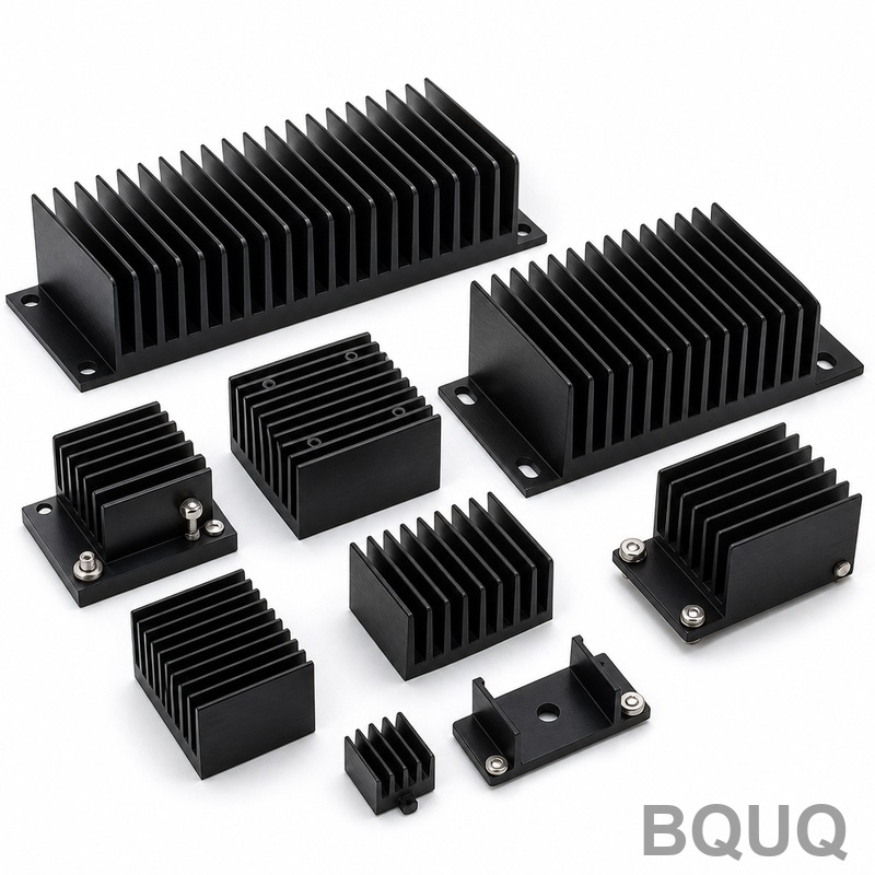
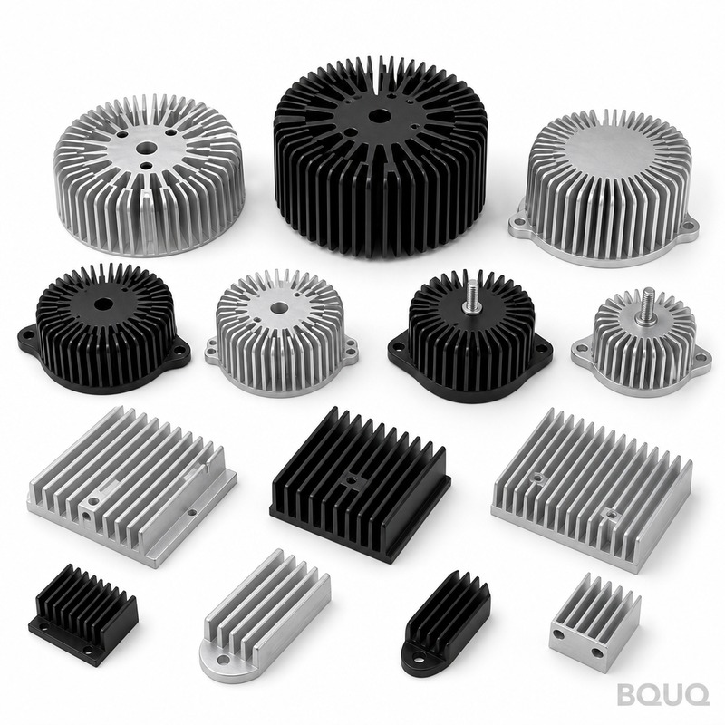
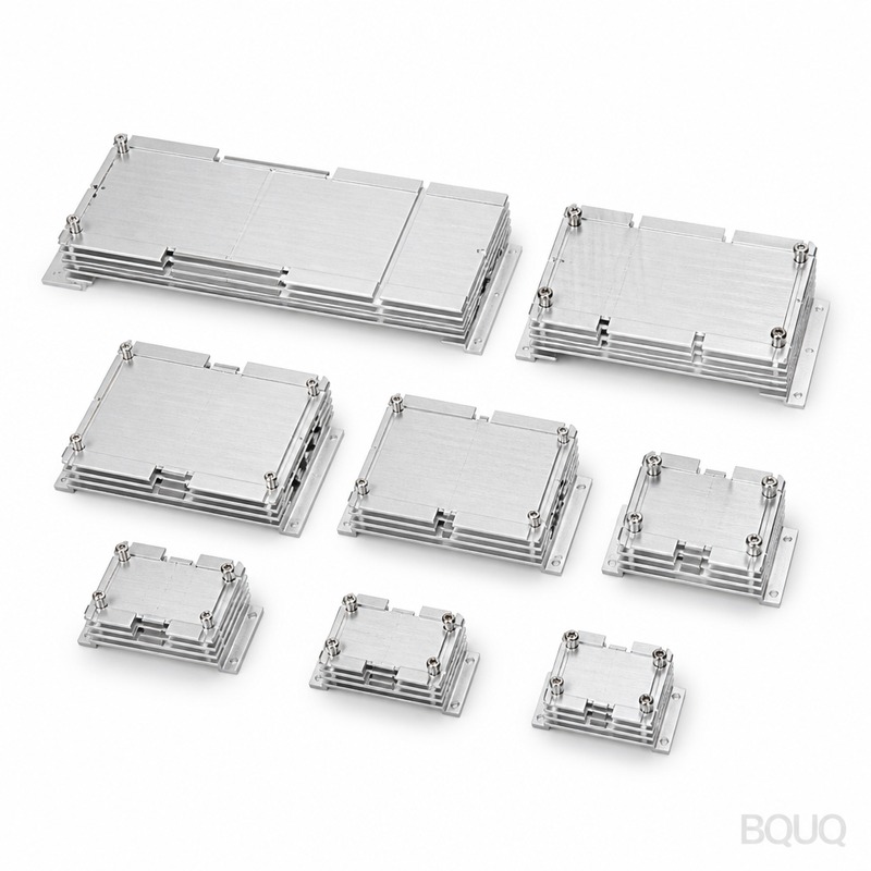
BQUQ Black Anodized Aluminum Heatsink Collection for Precision Thermal Management
Why This Heatsink Collection Runs Cooler Than Your Last Vendor This is a ready-to-order line of black anodized aluminum heatsinks machined to ±0.02 mm dimensional tolerance and 0.05 mm flatness runout
Get a Fast Quote for This Part
Send us your drawing / quantity / material — reply within 24h.
Why This Heatsink Collection Runs Cooler Than Your Last Vendor
This is a ready-to-order line of black anodized aluminum heatsinks machined to ±0.02 mm dimensional tolerance and 0.05 mm flatness runout. You get a consistent 8–12 μm anodized layer (hardness 300–400 HV) that resists corrosion and improves thermal emissivity by 15% over bare aluminum. Lead time is 12 days for standard sizes, 20 days for custom profiles. Precision manufacturing, made in China, with no MOQ on any catalog part.
How We Control Fin Depth and Airflow Geometry
Every fin in this collection is cut with 3-axis CNC mills running at 18,000 RPM spindle speed. Fin depth tolerance is held to ±0.03 mm, which matters because a 0.1 mm variation in fin depth changes thermal resistance by up to 8%. We measure each fin pitch with a laser micrometer at three points along the length. If the pitch drifts beyond 0.05 mm, the part is rejected, not reworked. For forced convection designs, we add a 2° draft angle on every fin to reduce air resistance without sacrificing surface area.
Materials and Anodizing Chemistry We Use
Base material is 6063-T5 aluminum, chosen for its 201 W/m·K thermal conductivity and excellent extrusion formability. For higher heat flux applications, we offer 6061-T6 with a 10% strength increase but 5% lower conductivity. The black anodizing is Type II sulfuric acid process, 8–12 μm thick, sealed in hot deionized water. This gives you a surface that passes 500-hour salt spray testing per ASTM B117. We do not use dye-only coloring—the black oxide layer is integral to the aluminum, so it will not chip or peel under thermal cycling from -40°C to +125°C.
Flatness and Mounting Surface Preparation
Thermal interface materials (TIM) fail when the heatsink base is not flat. We machine the mounting surface to 0.05 mm flatness across the entire base, then surface-grind it to Ra 0.8 μm finish. This reduces thermal contact resistance by 30% compared to a raw machined surface. For through-hole mounting, we counterbore to 0.02 mm depth tolerance so screw heads sit flush. If you specify a lap finish, we can bring Ra down to 0.4 μm, but that adds 3 days to lead time—most customers do not need it.
Inspection Before Every Shipment
Each heatsink goes through three checks. First, a CMM (coordinate measuring machine) verifies overall dimensions and hole positions to ±0.02 mm. Second, a profilometer measures surface finish on the base and fin tops. Third, an anodizing thickness gauge checks coating uniformity at five points per part. We include a digital inspection report with every order, traceable to our in-house lab. If you need PPAP Level 3, we can provide full documentation at no extra charge—just ask when you send your drawing.
Catalog Sizes and Custom Machining Options
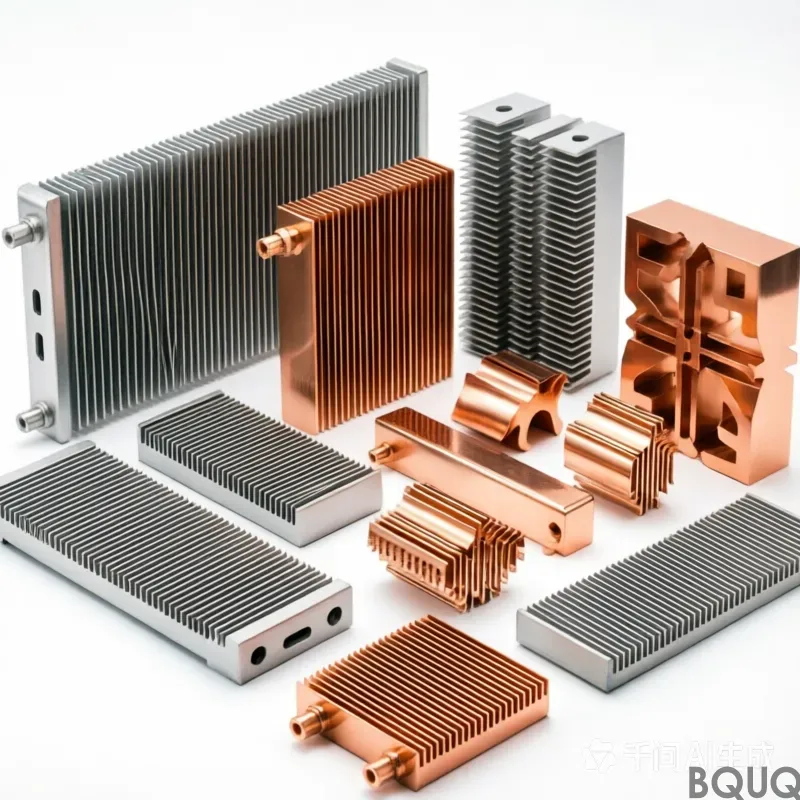
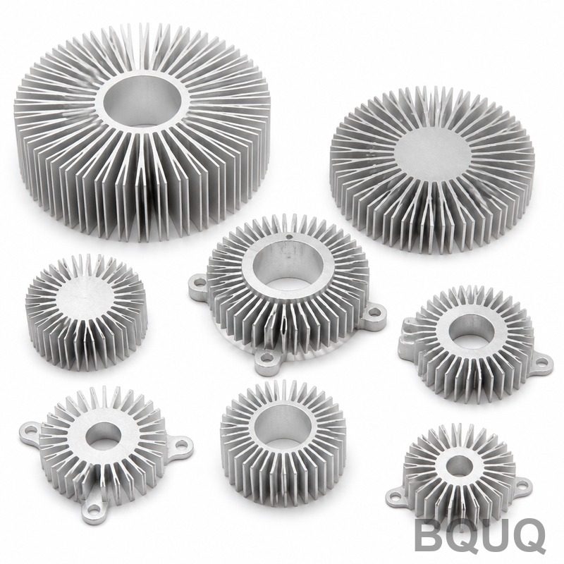
Standard collection includes 12 extrusion profiles: flat backs, pin fins, and folded fin arrays. Base sizes range from 25 mm × 25 mm to 300 mm × 300 mm. Fin heights go from 10 mm to 80 mm, and fin thickness from 1.5 mm to 4 mm. We stock 6063-T5 billets in all these profiles, so no MOQ means you can order a single piece for prototyping. Custom options include tapped holes (M2 to M8), spring-loaded clips, and pre-applied thermal tape. We also offer nickel-plated copper inserts for high-power IGBT modules—machined in the same run to avoid secondary assembly.
| Parameter | Specification | |---|---| | Base Material | 6063-T5 or 6061-T6 aluminum | | Anodizing Type | Type II sulfuric, black, sealed | | Anodizing Thickness | 8–12 μm (measured at 5 points) | | Surface Hardness | 300–400 HV on anodized layer | | Dimensional Tolerance | ±0.02 mm on all machined features | | Flatness (mounting base) | 0.05 mm total across base | | Surface Finish (base) | Ra 0.8 μm (ground), Ra 0.4 μm optional | | Fin Pitch Tolerance | ±0.05 mm | | Fin Depth Tolerance | ±0.03 mm | | Thermal Conductivity (base) | 201 W/m·K (6063-T5) | | Lead Time (standard) | 12 days | | Lead Time (custom) | 20 days | | MOQ | None (no MOQ on catalog parts) |
How to Match Fin Geometry to Your Power Budget
Do not guess—calculate. For natural convection, fin spacing should be 8–12 mm to avoid boundary layer overlap. For forced air at 2 m/s, you can drop to 4–6 mm spacing and increase fin height by 30% for the same footprint. Our engineers use CFD simulation for any custom design over 50 W dissipation. If you are unsure where to start, send us your heat load (W), ambient temperature, and maximum allowable junction temperature. We will return a fin geometry recommendation within 24 hours, free of charge. For machining parameters that affect your final part quality, refer to our CNC cutting tool selection guide—it covers toolpath strategies that directly impact fin surface finish. And if you are specifying tolerances tighter than ±0.02 mm, check our CNC machining tolerances guide to understand what is realistically achievable in production.
Packaging and Thermal Cycling Test Data
Heatsinks are packed individually in anti-static foam trays, then boxed with corrugated inserts to prevent fin bending during transit. We drop-test every box design at 1.2 meters onto concrete. For automotive or outdoor applications, we offer optional 100% thermal cycling verification—each part goes through 500 cycles from -40°C to +125°C with a 10-minute dwell. This test costs $0.50 per part and takes 3 extra days. We recommend it if your end product will see temperature swings greater than 60°C in service.
What is the minimum order quantity for this collection?
There is no MOQ—you can order one piece for prototyping or 10,000 pieces for production at the same unit price structure, with only a small setup fee for custom machining.
Can you customize fin height or add mounting holes?
Yes, we machine all standard profiles to your drawing—fin height, hole patterns, counterbores, and even odd-shaped bases are done in the same CNC setup with no extra lead time for up to 4 features.
How do you ensure black anodizing quality is consistent?
We run a test coupon with every batch, measure anodizing thickness at 5 points per part, and reject any part below 8 μm or above 12 μm—our rejection rate for coating issues is under 0.3%.
What is your lead time for a custom heatsink design?
Standard catalog parts ship in 12 days; custom designs with new machining or tooling take 20 days, including one free engineering consultation and DFM feedback within 24 hours of receiving your drawing.
Send Your Drawing for a Firm Quote Within 12 Hours
Email your STEP or PDF drawing to sc@bquq.com or message us on WhatsApp at +86 13713157787. We will reply with a firm price, exact lead time, and a DFM note on any potential tolerance risks—all within 12 business hours. For the Black Anodized Aluminum Heatsink Collection, we can quote from just a photo and rough dimensions, but a drawing with tolerances gets you the most accurate number. No MOQ, no hidden tooling fees, and every part ships with an inspection report.