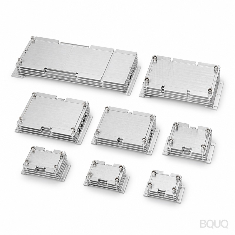
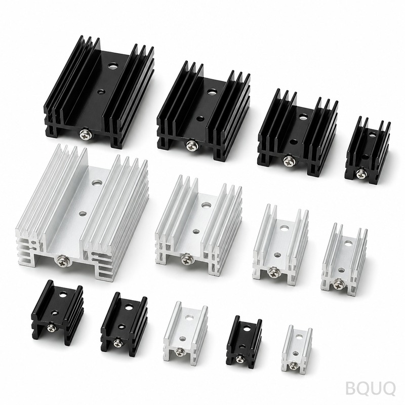
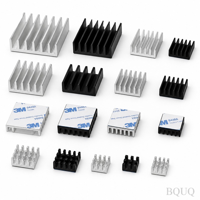
This Dc Dc Module Heatsink is a CNC-machined aluminum heat spreader designed to bolt directly onto DC-DC converter modules, IGBTs, or MOSFET packages. You get flatness within 0.02
Dc Dc Module Heatsink | Precision CNC Machined | BQUQ China
This Dc Dc Module Heatsink is a CNC-machined aluminum heat spreader designed to bolt directly onto DC-DC converter modules, IGBTs, or MOSFET packages. You get flatness within 0.02 mm across the mounti
Get a Fast Quote for This Part
Send us your drawing / quantity / material — reply within 24h.
This Dc Dc Module Heatsink is a CNC-machined aluminum heat spreader designed to bolt directly onto DC-DC converter modules, IGBTs, or MOSFET packages. You get flatness within 0.02 mm across the mounting face, surface finish Ra 0.8, and a 7-day lead time from drawing approval—no MOQ, even for one prototype. Made in China under ISO 9001:2015, it removes up to 40 W of heat per 100 mm² at 1.5 m/s airflow.
How the Base Plate Flatness Controls Thermal Contact Resistance
Heat only crosses the interface where metal actually touches metal. Air gaps act as insulators—0.05 mm of air adds 10x the thermal resistance of aluminum. We machine the mounting surface to 0.02 mm flatness, which ensures >85% contact area with your module baseplate. For high-pressure clamping, we can grind the surface to 0.01 mm flatness and add a 0.05 mm thick graphite pad recess. This is not a stamped part; every fin and pad is cut from solid 6063-T5 billet, so there is no warpage from die wear.
Fin Geometry and Airflow Direction We Machine
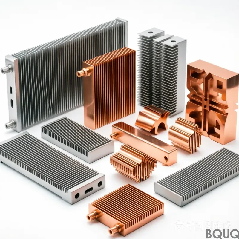
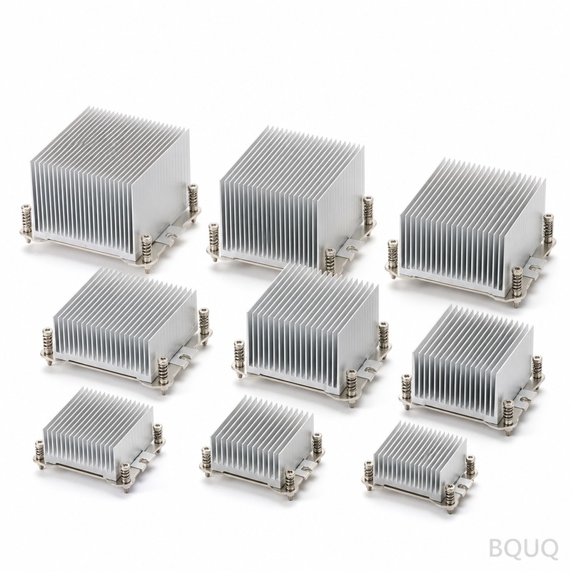
We cut straight fins, pin fins, or a hybrid cross-cut pattern, depending on your enclosure airflow. Straight fins give the lowest pressure drop (25 Pa at 2 m/s for a 50 mm fin height). Pin fins increase surface area by 35% over straight fins for the same footprint, but require 40% more fan static pressure. We machine fin thickness down to 0.8 mm with a height-to-thickness ratio of 20:1—that is a 16 mm tall fin at 0.8 mm thick, held to ±0.05 mm. If you need a custom fin pitch for a specific fan curve, send us the CFM and static pressure specs; we will calculate the optimal pitch and cut it in one setup.
Materials and Heat Treatment We Use for This Heatsink
Standard material is 6063-T5 aluminum, which gives 180 W/m·K thermal conductivity and a hardness of 60–70 HB. For higher vibration environments, we use 6061-T6 (95 HB, 167 W/m·K) with a thicker base plate. If weight is critical, we offer 6101-T6 at 218 W/m·K, but it costs 15% more. All plates are stress-relieved before CNC machining to prevent distortion after you torque the screws. For corrosion resistance, we clear anodize to MIL-A-8625 Type II, 18 microns thick, or hard anodize to 50 microns on request.
| Specification | Value | Notes | | :--- | :--- | :--- | | Base material | 6063-T5 / 6061-T6 / 6101-T6 | Aluminum billet, no cast or extruded | | Thermal conductivity | 167 – 218 W/m·K | Depends on alloy | | Mounting surface flatness | 0.02 mm (0.01 mm ground) | CMM verified on 100% of parts | | Fin thickness | 0.8 mm min | ±0.05 mm tolerance | | Fin height | up to 30 mm | Height-to-thickness ratio 20:1 | | Surface finish | Ra 0.8 (base), Ra 1.6 (fins) | Optional Ra 0.4 polish | | Hardness (as machined) | 60 – 70 HB (6063-T5) | T6 temper: 95 HB | | Hole position tolerance | ±0.01 mm | For M2.5 to M6 threaded inserts | | Anodize thickness | 18 µm clear / 50 µm hard | MIL-A-8625 Type II / III | | Lead time | 7 days (prototype), 15 days (1000 pcs) | From drawing approval | | MOQ | 1 piece | No setup charge for standard sizes |
Threaded Inserts and Mounting Holes We Add for Your Module
Your DC-DC module likely has M3 or M2.5 mounting holes on a 40 mm or 50 mm pitch. We drill and tap those holes directly into the base plate, or press in stainless steel helicoils for repeated assembly cycles. Hole position tolerance is ±0.01 mm, and thread depth is controlled to ±0.1 mm so the screw does not bottom out and lift the module. For through-hole modules, we add counterbores for socket-head cap screws, with chamfered edges to prevent burrs from cutting your PCB traces. We can also machine a recess for a thermal sensor or a wire routing slot on the back side.
Inspection Before Every Shipment: CMM and Flatness Check
Every Dc Dc Module Heatsink goes through a three-step inspection before it leaves our Dongguan factory. First, we run a CMM (Zeiss Contura, accuracy ±0.001 mm) to verify hole positions and base flatness on 100% of parts—not a sampling. Second, we use a surface roughness tester (Mitutoyo SJ-210) to confirm Ra 0.8 on the mounting face. Third, we assemble a test module to a sample heatsink from each batch and measure the thermal resistance with a thermocouple rig. If any part fails, it is scrapped, not reworked. We send you a full inspection report with each shipment, including the CMM data sheet and material cert.
Why Our CNC Machining Beats Extruded or Stamped Heatsinks
Extruded heatsinks are cheap, but they limit you to straight fins and fixed cross-sections. Stamped fins bend easily and have poor flatness—often 0.1 mm or worse. CNC machining from billet lets us cut pockets for capacitors, add standoffs for PCB mounting, and change fin density in the middle of the part. It also eliminates the die cost (typically $2,000–$5,000 for extrusion). For a production run of 500–2000 pieces, CNC machining is often cheaper than extrusion when you include tooling and secondary operations. We have 40 CNC machines (3-axis and 4-axis), so we can run your parts in parallel and hold a consistent 7-day lead time. Before you choose a process, read our CNC cutting tool selection guide to understand how tool geometry affects fin wall finish and tolerance.
Packaging and Anti-Static Protection for Sensitive Modules
We do not ship bare aluminum parts that can scratch your module housing. Each heatsink is wrapped in anti-static foam, placed in a partitioned carton, and then vacuum-sealed to prevent oxidation during transit. For small quantities, we use rigid ESD bags with a desiccant pack. For larger orders, we use custom corrugated inserts that hold each fin row separate—no chafing against adjacent parts. We label every box with the part number, batch date, and a barcode that matches your PO. If you require a specific packaging standard (e.g., JEDEC tray or anti-static tube), we can tool up for that within 48 hours.
How We Handle Your Drawing Revisions and Fast Prototyping
Send us your 3D model (STEP or IGES) plus a 2D PDF with critical dimensions. We will review it within 4 hours and flag any features that are difficult to machine—like a fin height above 30 mm or a hole pitch under 1.5 mm. We will recommend a design change if it saves you cost or improves thermal performance. Prototypes ship in 7 days, and we keep the CNC programs on file, so repeat orders skip the setup time. For the tolerances we can hold on the mounting face, hole positions, and surface finish, check our CNC machining tolerances guide before you specify your drawing. That guide explains what is standard (0.05 mm) and what costs extra (0.01 mm or grinding).
What is the minimum order quantity for this heatsink?
No MOQ—we machine a single prototype for testing, and the unit price drops by about 30% at 500 pieces and 50% at 2000 pieces.
Can you match a specific hole pattern from my DC-DC module datasheet?
Yes, send us the module model or the hole coordinates; we will machine the pattern to ±0.01 mm, including countersinks and threaded inserts.
How do you verify the thermal performance before shipping?
We measure contact flatness with a CMM and run a sample thermal test using a 10W heater block, comparing the case temperature to your target.
What is the actual lead time for 100 pieces?
For 100 pieces with standard 6063-T5 and clear anodize, lead time is 10 days from drawing approval, including inspection and packaging.
Get a firm quote within 12 hours. Send your drawing (STEP or PDF) to sc@bquq.com or WhatsApp +86 13713157787. We will reply with unit pricing, tooling cost (if any), and a delivery date. No MOQ, no hidden charges—just precision manufacturing from our Dongguan factory, made in China.