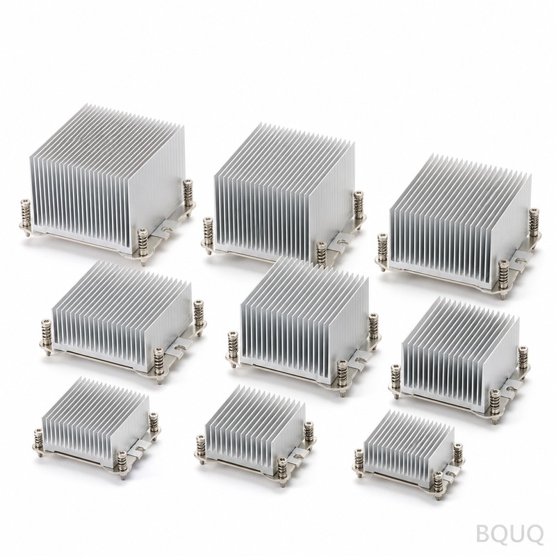
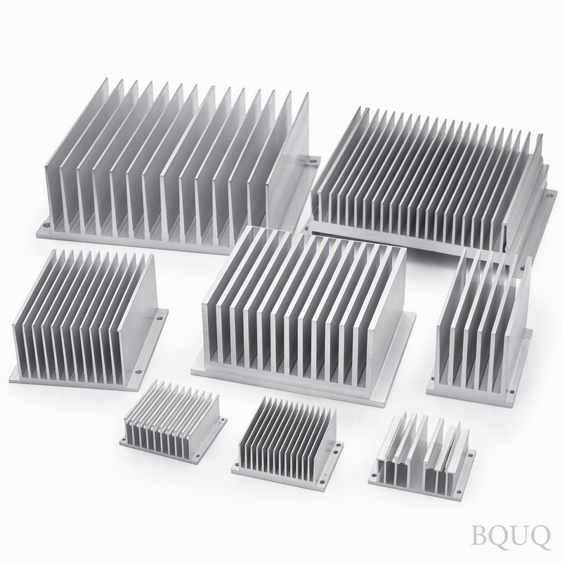
What This Cooler Does Differently: Flatness You Can Measure This CPU Heatsink Aluminum Cooler is a CNC-machined aluminum base with an optimized fin array, built to pull heat off
BQUQ CPU Heatsink Aluminum Cooler | Precision CNC Machining, Made in China
What This Cooler Does Differently: Flatness You Can Measure This CPU Heatsink Aluminum Cooler is a CNC-machined aluminum base with an optimized fin array, built to pull heat off a processor die and
Get a Fast Quote for This Part
Send us your drawing / quantity / material — reply within 24h.
What This Cooler Does Differently: Flatness You Can Measure
This CPU Heatsink Aluminum Cooler is a CNC-machined aluminum base with an optimized fin array, built to pull heat off a processor die and dump it into moving air. The concrete benefit is in the numbers: we hold base flatness to 0.01 mm total, fin pitch tolerance to ±0.05 mm, and surface finish at Ra 0.8 µm—so your thermal interface material works at full contact, not at 70% efficiency. Lead time is 7 days for prototypes, 15 days for production runs, and we ship from Dongguan with 20 years of precision manufacturing behind every batch.
This is not an extruded shelf part. It is a machined cooler, which means we can cut the fin geometry to your exact airflow direction, add mounting bosses, or change the base thickness without paying for a new extrusion die. You get the thermal performance of a custom design at a price close to a stock cooler, because our CNC spindles run 24/7 and we batch similar jobs together.
Fin Geometry and Airflow Direction: We Cut Fins, Not Just Bases
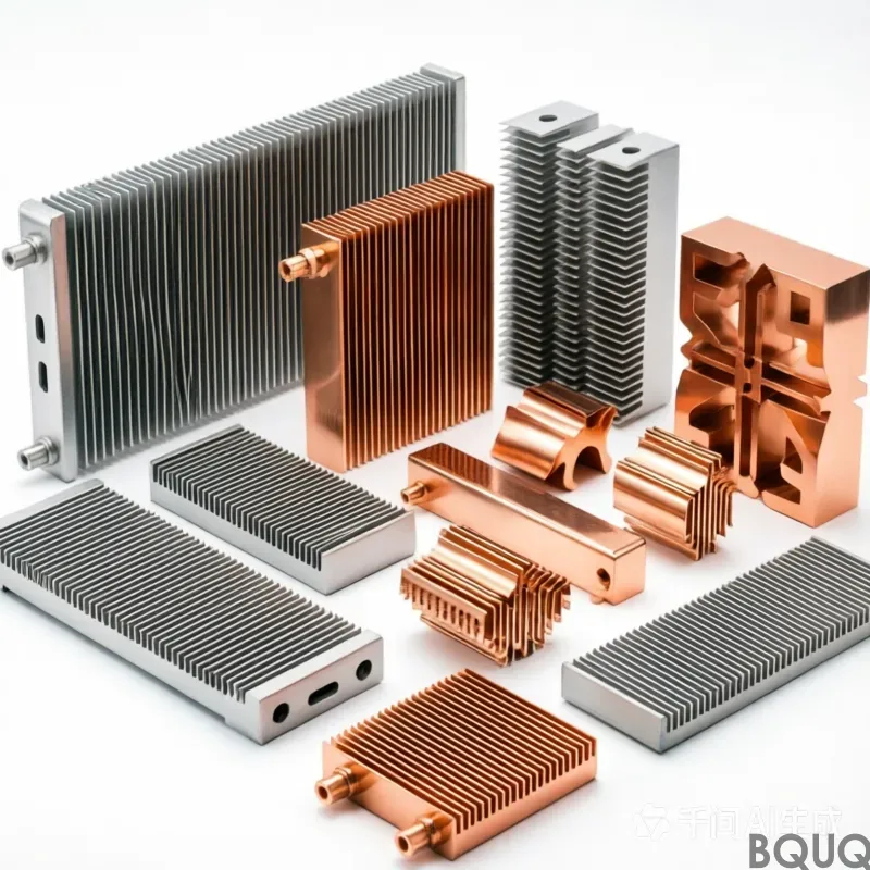
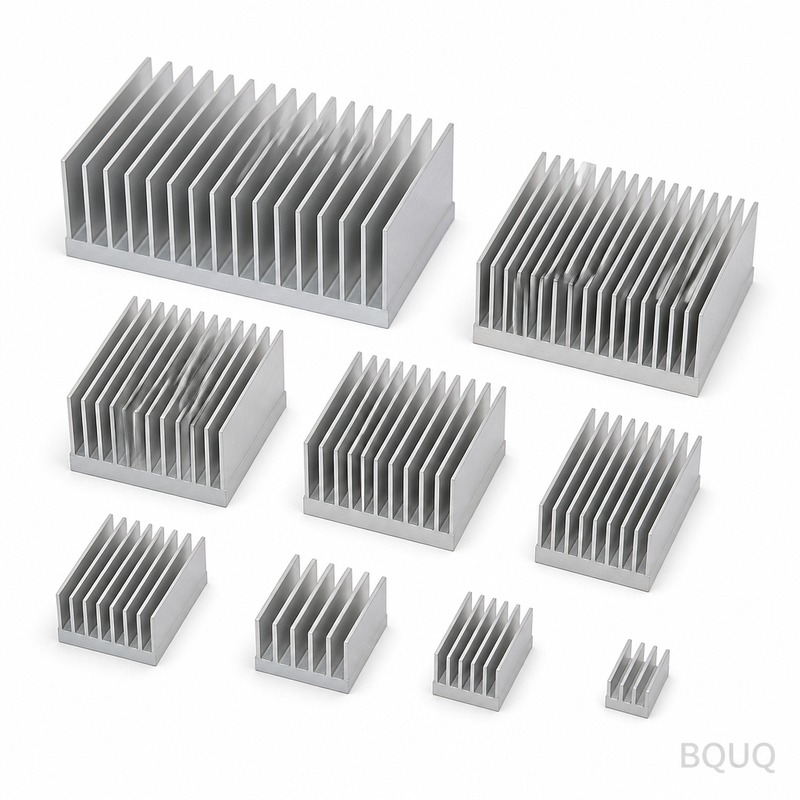
Most aluminum coolers are extruded, which forces every fin to run parallel in one direction. Our CNC process allows radial, stepped, or split fin arrays. You want a 45-degree angled fin to match a blower fan? We cut it. You need a 3 mm gap between fins for low static pressure fans? We hold that gap to ±0.05 mm across the entire block. Fin thickness can go down to 0.8 mm with a height-to-thickness ratio of 20:1, which means more surface area per square centimeter of base—that is where your thermal resistance drops.
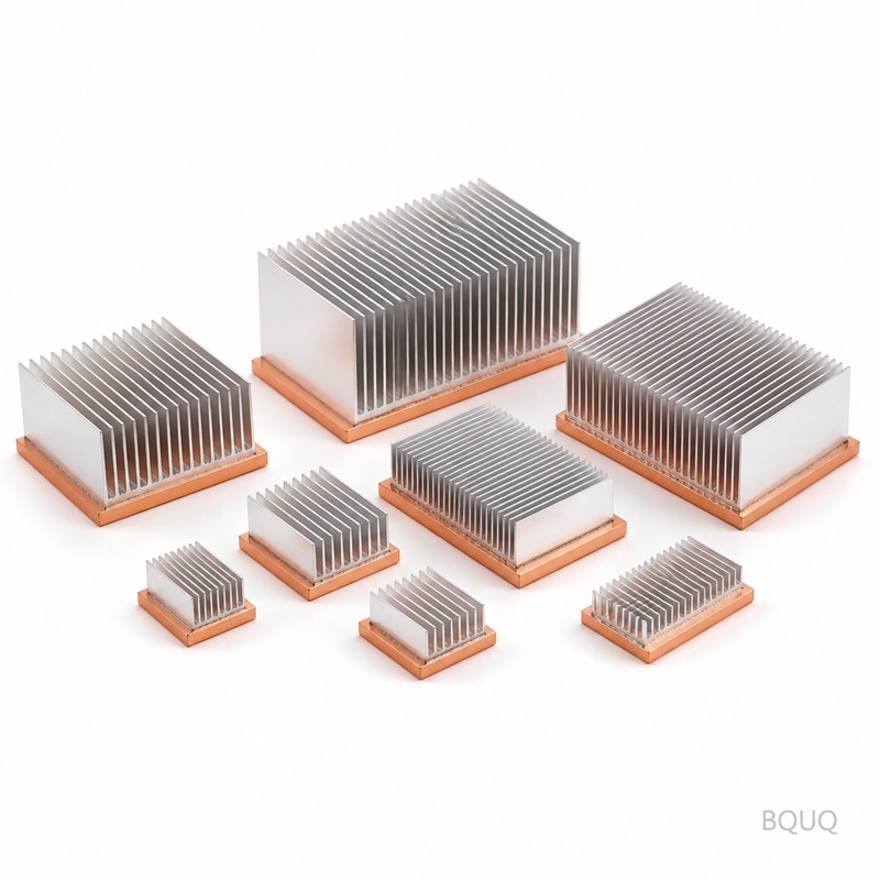
We also machine the base and fins from a single billet of 6061-T6 or 6063-T5 aluminum. No soldered joints, no thermal interface layer between fin and base. The heat path is continuous metal, so there is no added thermal resistance at a joint. If you need a copper insert for the die contact area, we can press-fit or braze a C1100 copper slug into the aluminum base—this is common for high-Watt processors.
Materials and Heat Treatment We Use for This Cooler
We stock 6061-T6 (yield strength 276 MPa) and 6063-T5 (better for thin fins, yield 145 MPa) in plate and billet form. For high-frequency switching applications where the cooler also acts as a structural mount, we can specify 6082-T6. All material comes with a mill certificate; we verify hardness on every incoming lot using a Rockwell tester—expect 8–12 HRC for 6061-T6, which is not hard but is stable under thermal cycling.
If you need a hard anodize coating (MIL-A-8625 Type III), we apply 25–50 µm thickness, which raises surface hardness to 60+ HRC equivalent for wear resistance. For bare aluminum, we offer a clear chromate conversion coating (MIL-DTL-5541) to prevent oxidation before you mount the cooler. We do not paint heat sinks—paint acts as an insulator.
For the CNC cutting tools themselves, our shop uses the same logic you do when selecting a tool for your own parts. If you are machining aluminum in-house, review our CNC cutting tool selection guide to match feed rates to your spindle. For the tolerances we hold on this cooler, see our CNC machining tolerances guide to understand what is possible beyond our standard 0.01 mm.
Inspection Before Every Shipment: Flatness, Fin Pitch, and Surface Check
Every CPU Heatsink Aluminum Cooler goes through a 3-step inspection before it leaves our floor. Step one: a CMM (coordinate measuring machine) probe checks base flatness across 9 points—we reject anything above 0.012 mm, even though we promise 0.01 mm. Step two: a comparator or optical measurement verifies fin pitch and thickness at three locations (front, middle, back) to ensure the fins did not bend during machining. Step three: a surface roughness tester measures Ra on the base contact area; we target 0.8 µm, and if you request a mirror polish for liquid metal TIM, we can hit Ra 0.2 µm.
We also do a thermal test on one sample per batch if you provide a heat source specification. We mount a dummy die, run a thermocouple at the base center, and record the thermal resistance in °C/W at a fixed airflow. You get that report with your shipment. No guesswork.
Stamping and Spring Options for Mounting Clips
Because we are not only a CNC shop—we also run stamping and spring lines—we can manufacture the mounting clip or spring-loaded push-pin hardware in the same factory. This saves you a second supplier and a second shipping cost. The clip is typically 301 stainless steel, 0.4 mm thick, formed to a 45° bend with a tolerance of ±0.1 mm. The spring for a push-pin is 302 stainless wire, 0.6 mm diameter, with a load of 5–8 N at 2 mm deflection. We test spring force on a load tester for every batch.
If you have a plastic frame or backplate, we do not mold plastic, but we can machine an aluminum backplate or a Delrin prototype for you to test the assembly. Our stamping capability means we can also make a thin shim (0.05 mm thick) to adjust mounting height if your processor socket has a non-standard Z-height.
Volume, MOQ, and Lead Time: We Mean 'No MOQ'
We say no MOQ, and we mean it. Order one unit for a prototype, or 10,000 for a production build. The price per unit drops predictably because we amortize setup time—a single cooler costs $18–$25 depending on size and finish; a 500-piece order drops to $6–$9 per unit. Lead time is 7 days for a single piece, 15 days for up to 2,000 pieces, and 25 days for 10,000 pieces (we run 20 CNC machines in two shifts).
For standard sizes (40×40 mm, 50×50 mm, 80×80 mm base), we keep raw 6061 billets in stock. For custom sizes, we add 2 days for material procurement. If you need a specific anodize color (black, red, blue), we run a batch anodize line every Wednesday and Friday, so add 3 days to your lead time.
Thermal and Mechanical Spec Table for This CPU Heatsink Aluminum Cooler
Parameter
Value
Notes
Material
6061-T6 or 6063-T5
Mill cert provided per lot
Hardness (base)
8–12 HRC (6061-T6)
Rockwell B scale
Base flatness
0.01 mm total
9-point CMM check
Fin pitch tolerance
±0.05 mm
Optical measurement
Fin thickness (min)
0.8 mm
Height/thickness ratio 20:1
Surface finish (base)
Ra 0.8 µm (option 0.2 µm)
For liquid metal TIM
Runout (mounting holes)
0.02 mm TIR
To socket datum
Anodize thickness
25–50 µm (Type III)
60+ HRC equivalent
Lead time (prototype)
7 days
Single piece
Lead time (production)
15–25 days
Up to 10,000 pcs
MOQ
No MOQ
1 piece accepted
What is the minimum order quantity (MOQ) for this CPU Heatsink Aluminum Cooler?
No MOQ—we machine a single prototype or 10,000 units at the same quality standard.
Can you customize the fin pattern and mounting holes for my specific socket?
Yes, we CNC machine any fin direction, hole pattern, or base thickness from your 3D model or 2D drawing, with no tooling change fees.
How do you control quality on a heat sink where flatness is critical?
We run a 9-point CMM flatness check, optical fin pitch verification, and surface roughness test on every part before packing.
What is the lead time if I need 500 pieces with black anodize?
15 days for machining plus 3 days for anodize, so 18 days total from drawing approval to shipment.
Get a Firm Quote Within 12 Hours
Send your drawing or a rough sketch with dimensions, target thermal resistance, and mounting requirements. We will reply with a firm price, a DFM check (we flag thin fins or tight tolerances that will drive cost up), and a delivery date. If your design needs a different material or a copper insert, we tell you the cost difference before you commit. Email sc@bquq.com or WhatsApp +86 13713157787. We are in Dongguan, China—same time zone as Hong Kong, so you get a response during your working day. All precision manufacturing is done in-house, made in China, with export experience to the US, EU, and Japan.