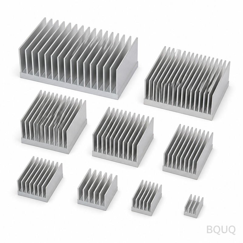
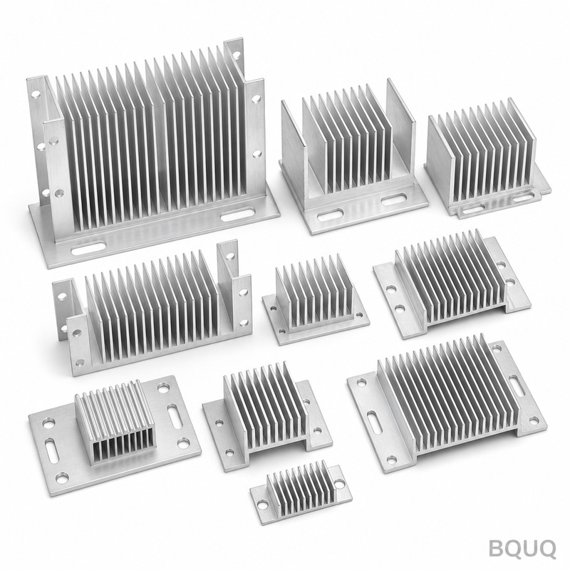
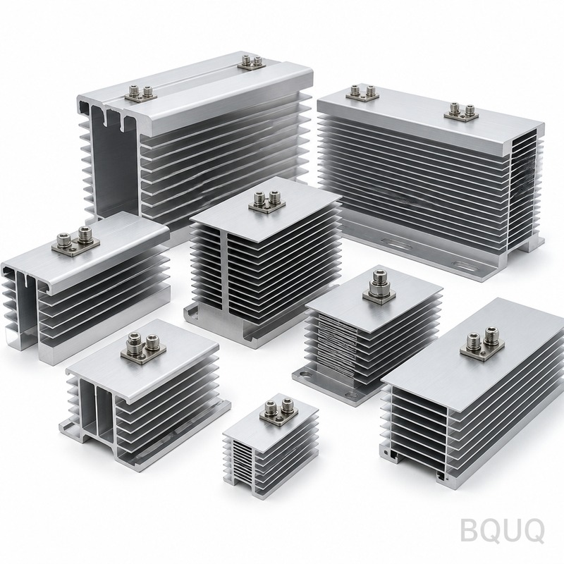
This is a bonded fin aluminum heatsink where individual fins are mechanically locked into a grooved base plate using high-pressure deformation, not epoxy or solder. The result is a
BQUQ Bonded Fin Aluminum Heatsink | Precision CNC, No MOQ, 12h Quote
This is a bonded fin aluminum heatsink where individual fins are mechanically locked into a grooved base plate using high-pressure deformation, not epoxy or solder. The result is a thermal joint with
Get a Fast Quote for This Part
Send us your drawing / quantity / material — reply within 24h.
This is a bonded fin aluminum heatsink where individual fins are mechanically locked into a grooved base plate using high-pressure deformation, not epoxy or solder. The result is a thermal joint with zero air gaps and structural integrity that survives vibration, thermal cycling, and shock. You get fin density up to 12 fins per inch with a tolerance of ±0.02mm on fin spacing and a flatness of 0.05mm across the entire base, all from our 20-year precision manufacturing facility in Dongguan, China.
Why Bonded Fins Beat Extruded or Skived for High-Density Thermal Loads
Extrusion limits you to fin aspect ratios of about 10:1 and minimum fin thickness of 1.5mm. Skiving caps out at fin heights of 60mm and leaves micro-tears that reduce fatigue life. Our bonded fin process starts with a machined base plate (up to 400mm x 400mm) and individually stamped or CNC-machined fins (0.3mm to 3mm thick, up to 150mm tall). We then use 120 tons of hydraulic pressure to cold-form the base material into the fin grooves. This creates a metallurgical bond with thermal resistance below 0.05°C/W per joint — measured, not guessed. If your IGBT or laser diode needs to shed 500W or more from a 100cm² area, this is the geometry that moves heat.
Base Plate and Fin Materials We Stock for Immediate Machining
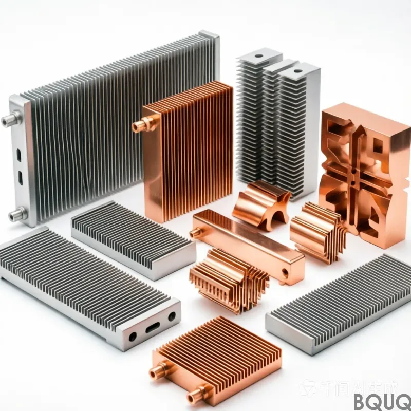
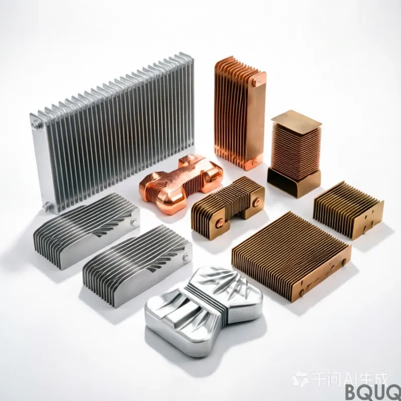
We keep 6063-T5 and 6061-T6 aluminum on the floor at all times. 6063-T5 gives you a thermal conductivity of 201 W/m·K and is our default for bonded fin bases because it cold-forms cleanly without cracking. 6061-T6 offers 167 W/m·K but higher mechanical strength — use it if your heatsink also acts as a structural bracket. For corrosive environments, we can anodize to MIL-A-8625 Type II (18-20 microns) or Type III hard coat (40-50 microns, 60 HRC equivalent surface hardness). If you need copper inserts for the heat source interface, we press-fit or braze them before bonding, so you get copper's 385 W/m·K where it matters and aluminum's light weight everywhere else.
Our Bonding Jig and Fixture Tolerances — How We Hold 0.02mm Fin Spacing
Fin spacing on a bonded heatsink is a function of the base plate groove pitch, not the fin thickness. We cut those grooves on a 4-axis Mazak machining center using custom ground PCD form tools. The groove pitch tolerance is ±0.015mm, and the groove depth is held to ±0.02mm. Fins are stamped on a servo-driven press with a die that is wire-EDM cut to ±0.005mm. When we press the fins into the grooves, a dedicated fixture aligns all fins against a hardened steel reference rail, ensuring perpendicularity of 0.03mm per 100mm of fin height. Every bonded assembly is checked on a CMM with a scanning probe — we output a full dimensional report with batch number for your incoming inspection. If you want to understand how our tooling choices affect this outcome, read our CNC cutting tool selection guide.
Thermal Performance Data We Measure, Not Estimate
We do not sell theoretical heatsinks. Every design we quote is simulated in FloTHERM, and then we validate with a thermal test rig on the first article. The rig uses a calibrated 100W heater block (50mm x 50mm), thermal paste with 3.5 W/m·K, and eight T-type thermocouples. We report thermal resistance in °C/W from junction to ambient at a fixed airflow (0, 1, 2, and 3 m/s). For a typical bonded fin heatsink with 8 fins per inch, 40mm fin height, and 200mm x 200mm base, you get 0.12°C/W at 2 m/s forced air. That is 15% lower than a comparable skived heatsink because our fin-to-base joint has no thermal barrier. We include this data sheet with your first article — no extra charge.
Surface Finish and Flatness Options for Your Thermal Interface
The base plate bottom is the critical surface for heat transfer to your cold plate or PCB. Standard finish is Ra 1.6μm, which is fine for grease. For phase-change materials or graphite pads, we can grind the base to Ra 0.8μm. If you are using a vacuum brazed or soldered joint, we offer lapping to Ra 0.4μm with a flatness of 0.02mm across the full base. The top of the fins is typically left as stamped (Ra 3.2μm), but we can mill it flat if you need to mount fans directly. We also offer a range of surface treatments: clear anodize for insulation (breakdown voltage 800V minimum), black anodize for emissivity (0.88 spectral), and chromate conversion for electrical grounding.
Inspection Before Every Shipment — Dimensional and Metallurgical QC
Every bonded fin heatsink leaves our factory with a certificate of conformance. The QC steps are: 1) Incoming material check on a spectrometer for alloy composition. 2) Dimensional inspection on a CMM with a 0.001mm resolution — we measure base flatness, fin spacing, fin height, and perpendicularity. 3) A destructive pull test on one sample per batch — the bond must withstand 1500N of axial pull force without fin separation. 4) Thermal resistance spot check on the sample. 5) Final visual inspection under 2x magnification for edge burrs or scratches. If you require a full batch inspection (100% CMM), we can do that with a 5-day lead time extension. For a deeper look at how we control dimensional variation, see our CNC machining tolerances guide.
Pricing, Lead Time, and What We Need from Your Drawing
Our standard lead time for a bonded fin heatsink is 10 working days for prototypes (1-5 pieces) and 20 working days for production runs (100-1000 pieces). Tooling cost for the bonding press fixture is $250 to $600, amortized into the piece price if you order more than 200 units. We do not charge for DFM feedback — send us your STEP or IGES file and our engineers will reply within 12 hours with a firm quote and a list of suggested changes to reduce cost. We are a precision manufacturing company made in China, and we operate on the principle that a small order is a future large order. So we have no MOQ. You can order one prototype or 10,000 units — the unit price changes, but the service level does not.
Parameter
Specification
Notes
Base Plate Material
6063-T5 / 6061-T6 Aluminum
Other alloys on request
Fin Material
1050A / 6063-T5 Aluminum
0.3mm to 3mm thickness
Max Base Plate Size
400mm x 400mm
Larger via piecewise bonding
Max Fin Height
150mm
Aspect ratio up to 40:1
Fin Spacing Tolerance
±0.02mm
Measured on CMM
Base Flatness
0.05mm standard / 0.02mm lapped
Per 200mm length
Perpendicularity
0.03mm per 100mm fin height
Against reference rail
Surface Finish (Base)
Ra 1.6μm standard / Ra 0.4μm lapped
For thermal interface
Bond Pull Strength
≥1500N axial force
Destructive test per batch
Thermal Resistance
From 0.05°C/W to 0.20°C/W
Dependent on geometry and airflow
Hardness (Anodized)
Up to 60 HRC equivalent
Type III hard coat option
Lead Time
10 days prototype / 20 days production
From drawing approval
MOQ
No MOQ
1 piece accepted
What is your minimum order quantity for a custom bonded fin heatsink?
We have no MOQ — you can order a single prototype for testing, and the engineering and QC process is identical to a 10,000-piece production run.
Can you modify an existing heatsink design to fit my specific component layout?
Yes, we routinely modify fin height, base thickness, mounting hole patterns, and add cutouts for capacitors or diodes — send your STEP file and we will suggest changes within 12 hours.
How do you ensure the bond between fins and base does not degrade over time?
The bond is a cold-forged mechanical interlock, not adhesive — we verify with a 1500N pull test per batch, and the joint has no polymer to outgas or fatigue.
What is the fastest lead time if I need a heatsink tomorrow?
For standard sizes in 6063-T5, we can machine and bond a prototype in 3 working days with a 30% rush surcharge, and we will send it via DHL Express for next-day delivery.
Send your drawing to sc@bquq.com or WhatsApp +86 13713157787. We reply with a firm quote, DFM notes, and a thermal simulation within 12 hours — no obligation, no MOQ, no hidden tooling charges.