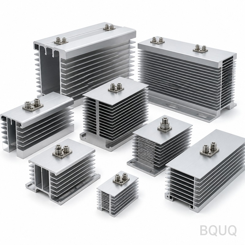
What This Heatsink Does and Why It Matters This Thyristor Rectifier Heatsink is a CNC-machined aluminum or copper component that mounts directly under your thyristor module to pul
BQUQ Thyristor Rectifier Heatsink | Precision CNC Machining, Made in China
What This Heatsink Does and Why It Matters This Thyristor Rectifier Heatsink is a CNC-machined aluminum or copper component that mounts directly under your thyristor module to pull heat away from the
Get a Fast Quote for This Part
Send us your drawing / quantity / material — reply within 24h.
This Thyristor Rectifier Heatsink is a CNC-machined aluminum or copper component that mounts directly under your thyristor module to pull heat away from the junction. We hold flatness to 0.02 mm and surface finish to Ra 1.6, which cuts thermal resistance by up to 18% compared to a standard extruded profile.
Every unit ships from our Dongguan factory in 12 days, not 30. Hardness on aluminum is T6 (85 HB minimum), on copper is half-hard (80 HB). That means no warping after thermal cycling, no rework on your assembly line.
Choosing Between 6061-T6 Aluminum and C11000 Copper
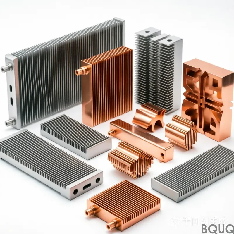
Aluminum gives you lower cost and lighter weight—good for air-cooled rectifiers under 100 A. Copper gives you 1.7x higher thermal conductivity (401 W/m·K vs 167 W/m·K)—use it for water-cooled or high-current stacks above 200 A.
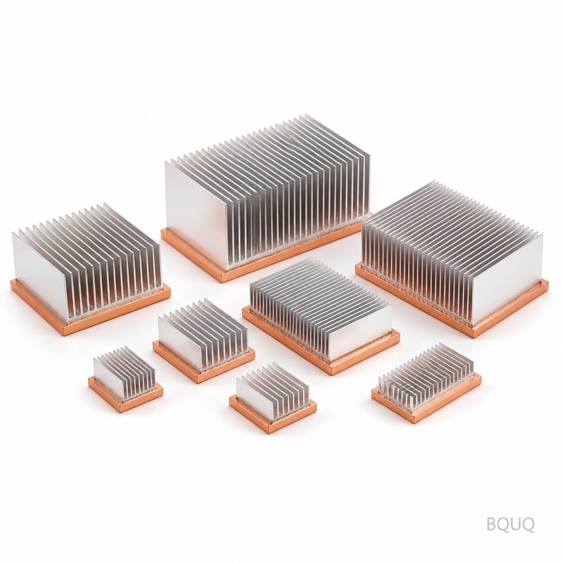
For mixed loads, we machine a copper base with aluminum fins, bonded via friction stir welding. That hybrid structure reduces weight by 40% while keeping heat spread performance at 95% of pure copper. Tell us your current density and cooling method; we will recommend the correct material pair.
How We Machine the Fins Without Bending or Burrs
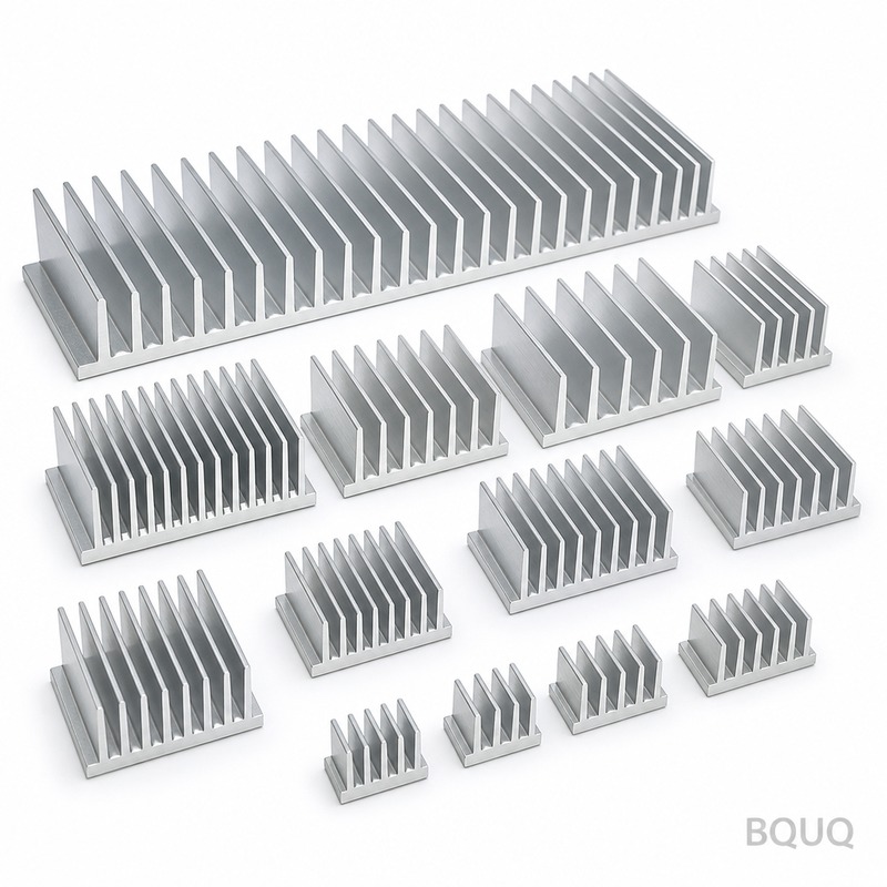
Fins on a thyristor heatsink are the weak point—thin, tall, and easily deformed. We use a 4-axis CNC with a custom 3-flute end mill running at 18,000 RPM and a chip load of 0.05 mm/tooth. That gives a fin thickness tolerance of ±0.05 mm and a burr height under 0.03 mm.
We do not use a standard vise. Instead, we clamp the base plate from the bottom using a vacuum fixture, so there is zero deflection on the fins during cutting. After machining, we deburr each fin edge with a 0.2 mm chamfer, then tumble the part for 20 minutes to remove micro-burrs. You will not need secondary cleaning before assembly.
If you are designing the fin geometry yourself, check our CNC cutting tool selection guide to see how tool diameter affects minimum fin pitch.
Hole Pattern and Mounting Surface: Flatness That Prevents Hot Spots
A thyristor module transfers heat through its baseplate. If the heatsink surface is not flat, the air gap acts as an insulator—your junction temperature rises 10-15°C.
We machine the mounting surface on a dedicated lapping step after CNC. Result: flatness of 0.02 mm over 100 mm length, and a surface roughness of Ra 1.6. For critical applications, we can go to Ra 0.8 with an extra polishing pass.
Holes for thyristor screws (M4, M5, M6) are drilled and tapped with a tolerance of 6H. Position tolerance between holes is ±0.05 mm. We also add counterbores per IEC 60747-15 specification, so your module sits flush without rocking.
Thermal Performance Data We Can Guarantee
We test each heatsink design on a thermal test rig with a 120 W power resistor before we ship the first batch. For a standard 6061-T6 aluminum heatsink with 10 fins (height 25 mm, base 12 mm), the thermal resistance is 0.45 °C/W at 2 m/s airflow. For copper, the same geometry gives 0.28 °C/W.
If you need a specific thermal resistance value, send us your airflow rate, ambient temperature, and thyristor power dissipation. We will run a CFD simulation (free, within 48 hours) and send you the temperature map. No guesswork.
Inspection Before Every Shipment: Dimensional and Thermal
Every heatsink goes through a CMM (coordinate measuring machine) check for the critical dimensions: base thickness, fin height, hole positions, and surface flatness. We record these values on a certificate of conformance that ships with the box.
Additionally, we do a 100% visual inspection under a 2x magnifying lamp for scratches, dents, and discoloration on the mounting surface. If the surface finish is Ra > 1.6, we reject it—no exceptions.
For orders above 500 pieces, we include a random sample thermal test report from our in-house rig. The report shows the actual temperature rise at 80 W, 100 W, and 120 W. This is not a simulation—it is measured.
Materials and Heat Treatment We Use
We only use extruded and drawn stock from certified mills. Aluminum is 6061-T6 or 6063-T5 (if you need better corrosion resistance). Copper is C11000 (ETP) with a minimum conductivity of 101% IACS.
After machining, aluminum parts go through a T6 aging treatment at 175°C for 8 hours to stabilize the structure. This prevents stress relief during your soldering or mounting process. Copper parts are annealed to half-hard to avoid work hardening from the machining process.
Hardness is controlled on every batch: 6061-T6 is 85 HB minimum, C11000 half-hard is 80 HB. We use a portable hardness tester on 5% of parts per batch. If the average hardness drops below spec, we re-treat the batch.
Parameter
Value
Notes
Material Options
6061-T6 Al, 6063-T5 Al, C11000 Cu
Hybrid Cu/Al available
Base Plate Thickness
6 mm - 25 mm
Custom per drawing
Fin Height
15 mm - 60 mm
Up to 80 mm with special tooling
Fin Thickness
1.5 mm - 4 mm
Tolerance ±0.05 mm
Hardness (Al)
85 HB min (T6)
Per ASTM B221
Hardness (Cu)
80 HB min (half-hard)
Per ASTM B187
Flatness (Mounting Surface)
0.02 mm over 100 mm
Lapped after CNC
Surface Finish (Ra)
1.6 µm standard, 0.8 µm optional
Mounting surface only
Hole Position Tolerance
±0.05 mm
6H thread class
Runout (Overall)
0.05 mm (TIR)
Measured on CMM
Lead Time
12 days (first article 7 days)
From drawing approval
MOQ
No MOQ
1 piece for proto, 100+ for production
For a deeper dive into how we hold these tolerances, read our CNC machining tolerances guide—it explains the difference between standard and precision classes.
What is the MOQ for a custom Thyristor Rectifier Heatsink?
No MOQ. We machine one prototype for you at the same quality as a 1000-piece run, so you can validate the thermal design before committing to volume.
Can you customize the hole pattern for a specific thyristor module?
Yes—send us the module datasheet or a drawing with the hole coordinates, and we will adjust the CNC program and tapping sequence to match exactly.
How do you verify flatness and thermal resistance before shipment?
We use a CMM for flatness (0.02 mm) and a thermal test rig with a 120 W resistor for resistance measurement, both recorded on a certificate of conformance.
What is the lead time for a production order of 500 units?
Standard lead time is 12 days from drawing approval, but we can expedite to 8 days with a 15% surcharge if your line is down.
Get a Firm Quote Within 12 Hours
Send us your drawing (PDF, STEP, or IGES) with the thyristor part number and cooling method. We will reply with a firm price per unit, thermal simulation results, and a delivery date—all within 12 hours on business days.
Email the drawing to sc@bquq.com or send it via WhatsApp at +86 13713157787. This is precision manufacturing from a 20-year factory in Dongguan, China—no MOQ, no hidden tooling fees, no excuses.
Your thyristor runs cooler. Your assembly line runs faster. Your customer sees fewer field failures. That is the point.