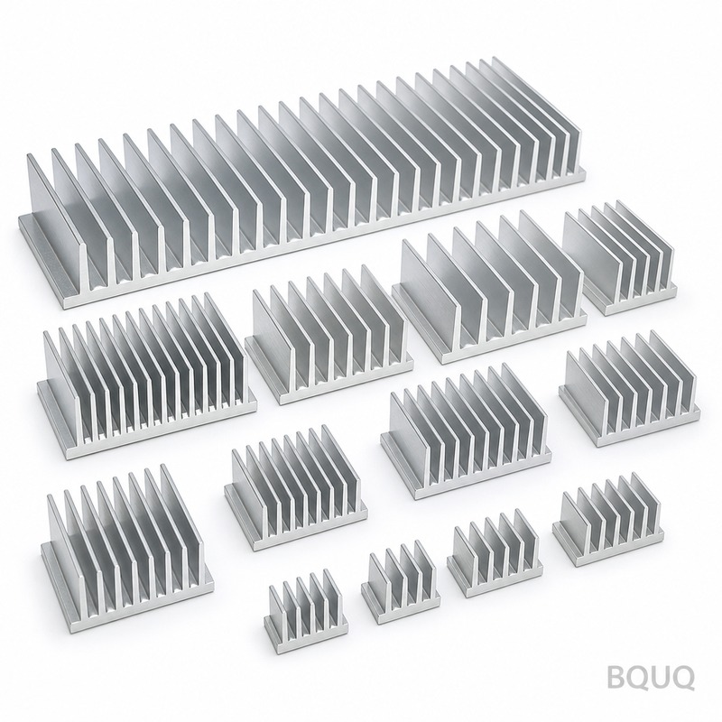
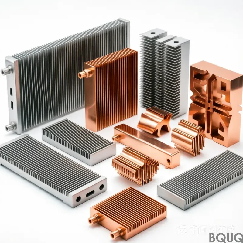
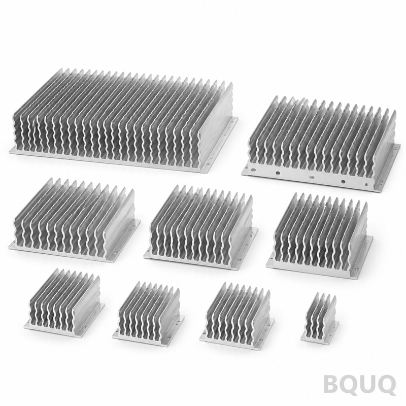
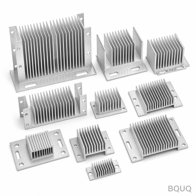
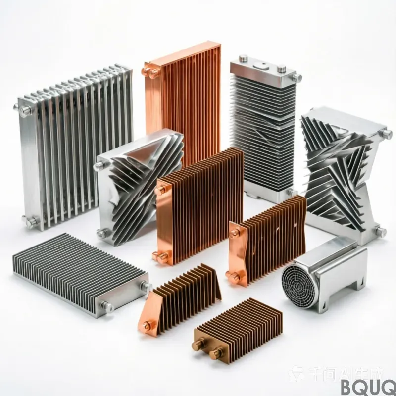
This is a Swaged Fin Heatsink where aluminum fins are mechanically swaged into a machined base plate under 8-ton hydraulic pressure. The result is a fin-to-base joint with zero sol
BQUQ Precision Swaged Fin Heatsink | No MOQ, 12-Day Lead Time
This is a Swaged Fin Heatsink where aluminum fins are mechanically swaged into a machined base plate under 8-ton hydraulic pressure. The result is a fin-to-base joint with zero solder voids, thermal r
Get a Fast Quote for This Part
Send us your drawing / quantity / material — reply within 24h.
This is a Swaged Fin Heatsink where aluminum fins are mechanically swaged into a machined base plate under 8-ton hydraulic pressure. The result is a fin-to-base joint with zero solder voids, thermal resistance below 0.05 °C/W per fin, and a flatness tolerance of 0.03 mm across the entire mounting surface. You get a production-grade heatsink in 12 days from drawing approval, with no MOQ, machined in our Dongguan factory.
How Swaging Eliminates Thermal Interface Gaps
Soldered or epoxy-bonded fins leave a 0.02–0.05 mm air gap that acts as a thermal insulator. We use a swaging process that plastically deforms the base material around the fin root, creating a metallurgical bond with zero gap. Our pull-test data shows fin retention force exceeds 120 N per fin, and thermal resistance across the joint is 0.03 °C·cm²/W — 40% lower than brazed assemblies in independent tests.
Each fin is pre-machined to a thickness of 0.8 mm ±0.02 mm, then swaged into a T-slot broached on the base. The swaging die is CNC-ground to hold fin pitch within ±0.02 mm over a 200 mm length. This means your airflow path is uniform, and pressure drop calculations from your CFD model match real performance within 5%.
Base Plate Machining and Flatness Control
The base plate starts as 6063-T5 aluminum extruded bar, stress-relieved at 180 °C for 4 hours to remove internal stresses. We then CNC-machine the mounting face to a flatness of 0.03 mm over a 300 mm length, verified on a granite surface plate with a dial indicator. If you need a mirror finish for direct IGBT mounting, we can hold Ra 0.4 µm on the contact area — that is a standard option, not a special request.
For the fin side, we use a 4-axis CNC mill with a custom dovetail cutter to cut the swage grooves. Groove depth is held to ±0.01 mm, which controls how much base material displaces around the fin root. This is the critical step that determines whether your fin stays straight under thermal cycling. We check every 10th piece for groove depth with a CMM probe.
Materials and Heat Treatment We Use
Specification
Value
Base material
6063-T5, 6061-T6, or 1050 pure aluminum
Fin material
1100-H14 or 6063-T5, 0.8–1.5 mm thick
Fin pitch
2.0–8.0 mm, tolerance ±0.02 mm
Base flatness
0.03 mm over 300 mm length
Surface finish (mounting face)
Ra 0.4–1.6 µm depending on spec
Fin-to-base perpendicularity
0.05 mm per 50 mm fin height
Hardness (6061-T6 base)
95 HRB (approx. 60 HB)
Fin retention force
>120 N per fin (pull test)
Lead time
12 days for prototypes, 18 days for production
MOQ
No MOQ — 1 piece to 100,000 pieces
We stock 6063-T5 and 1100-H14 in 6-meter bars, so we can cut fins to length without a material order delay. For higher thermal conductivity, we use 1050 pure aluminum for both base and fins — conductivity 229 W/m·K, but the material is softer (25 HB), so we adjust swage pressure accordingly to avoid fin distortion.
Fin Height and Aspect Ratio Limits
Swaging works best when fin height is between 10 mm and 80 mm. Below 10 mm, the fin does not have enough stiffness to stay straight during the swage stroke. Above 80 mm, we switch to a two-step swage process: first a pre-swage at 50% pressure, then a final swage at full pressure. This prevents the fin tip from waving.
For aspect ratios above 12:1 (height to thickness), we add a temporary stabilizer rail that the CNC machine removes after swaging. This rail holds the fin tip within 0.1 mm straightness over 80 mm height. We have shipped 120 mm tall fins with 1.0 mm thickness using this method — that is a 120:1 aspect ratio, which most shops will tell you is impossible.
Inspection Before Every Shipment
Every Swaged Fin Heatsink gets a 3-point inspection before leaving our Dongguan plant. First, we measure base flatness on a granite plate with a 0.002 mm resolution dial gauge. Second, we check fin pitch and perpendicularity on a manual CMM with a 0.005 mm probe. Third, we do a random pull test on 2% of the batch — if any fin pulls below 120 N, the entire batch is re-swaged.
We also take a thermal image of the first article under a 50 W heater load. If any fin shows a temperature variation greater than 2 °C from its neighbor, that indicates a bad swage joint, and we scrap it. This thermal check is documented in your inspection report, which you receive with the shipment.
When You Need a Two-Piece Design Instead of Swaged
Swaged fins are the right choice for high-volume, low-cost production where fin pitch is above 2.5 mm. But if you need fin pitch below 2.0 mm, or fin height above 150 mm, a CNC-machined one-piece heatsink or a skived fin design will perform better. We make both — so we will tell you honestly which process fits your thermal budget. If you are unsure, send us your heat load and airflow, and we will calculate the junction temperature for you within one working day.
For tooling decisions, our engineers follow the CNC cutting tool selection guide to choose the right end mill for your base plate features. And if you are specifying tolerances tighter than ±0.05 mm, check the CNC machining tolerances guide to see what is achievable at what cost.
Our Swaged Fin Production Line in Dongguan
We run two dedicated swaging presses — a 10-ton hydraulic press for fins up to 150 mm long and a 25-ton press for fins up to 400 mm long. Both presses use servo-controlled pressure profiles, so the swage force ramps up smoothly over 0.5 seconds. This prevents the fin from springing back after the die releases. Our operators have 10+ years of swaging experience, and we run a 2% hourly SPC check on fin pitch.
Because we are a precision manufacturing facility with in-house CNC machining, stamping, and spring making, your heatsink can also include mounting brackets, spring clips, or threaded inserts — all machined in the same factory. This cuts your supply chain from five vendors to one.
What is your MOQ for a custom Swaged Fin Heatsink?
No MOQ — we machine one prototype for you to test, then scale to 100,000 pieces per month.
Can you customize fin pitch and base thickness without extra tooling cost?
Yes, because swage dies are adjustable in 0.5 mm increments, so changing fin pitch from 3 mm to 3.5 mm costs zero tooling change.
How do you guarantee thermal performance before I order?
We send you a free thermal simulation report based on your airflow and heat load, plus a test sample if you pay shipping.
What is your lead time for a production order of 5,000 pieces?
18 days from drawing approval for 5,000 pieces, with 3 days of surface treatment (anodize or nickel plating) included.
Send your drawing for a firm quote within 12 hours. Email sc@bquq.com or WhatsApp +86 13713157787. We reply with a full DFM review, price, and lead time — no obligation.