Why This Heatsink Collection Eliminates Your Secondary Assembly Step Aluminum Heatsink With Mounting Base Collection 02 is a pre-engineered family of cooling components where the
BQUQ Aluminum Heatsink With Mounting Base Collection 02 | Precision CNC
Why This Heatsink Collection Eliminates Your Secondary Assembly Step Aluminum Heatsink With Mounting Base Collection 02 is a pre-engineered family of cooling components where the fin array and the m
Get a Fast Quote for This Part
Send us your drawing / quantity / material — reply within 24h.
Why This Heatsink Collection Eliminates Your Secondary Assembly Step
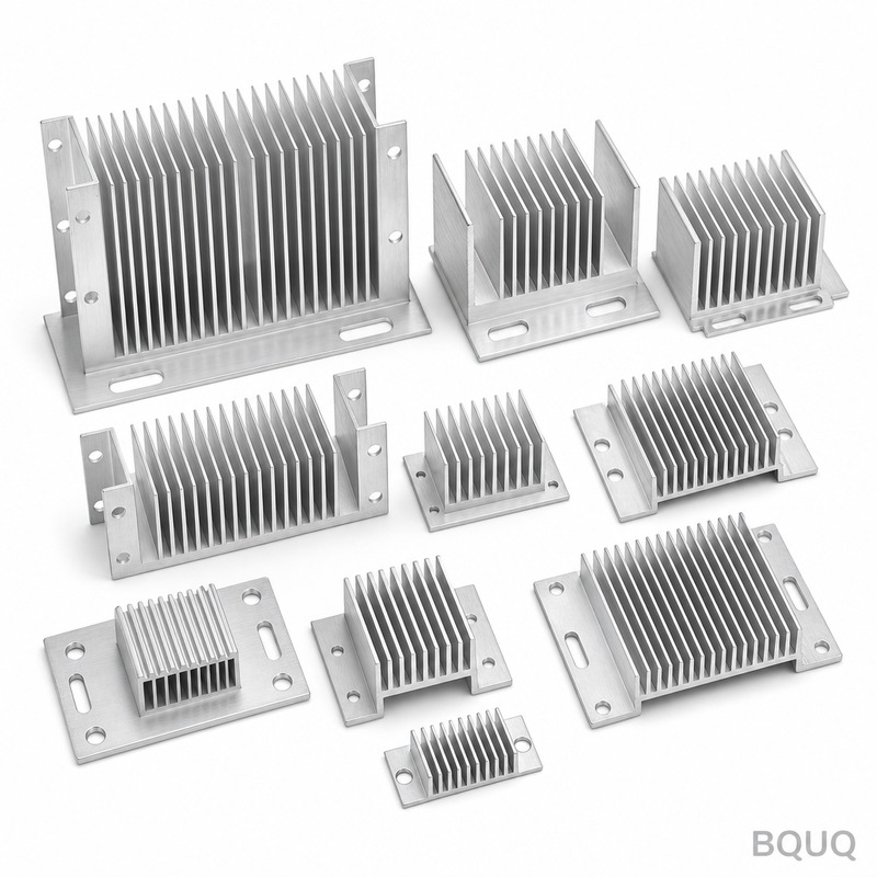
Aluminum Heatsink With Mounting Base Collection 02 is a pre-engineered family of cooling components where the fin array and the mechanical mounting flange are machined from a single aluminum billet. You skip the alignment, the thermal interface gap, and the extra procurement lead time that comes with bolting a separate base plate to a fin stack. Every unit ships with a flatness of 0.05 mm across the mounting surface and a fin-to-base perpendicularity of 0.08 mm, so your power transistor or IGBT sits on a true reference plane from the first trial run.
Machined from 6063-T5 or 6061-T6: You Choose the Yield Strength
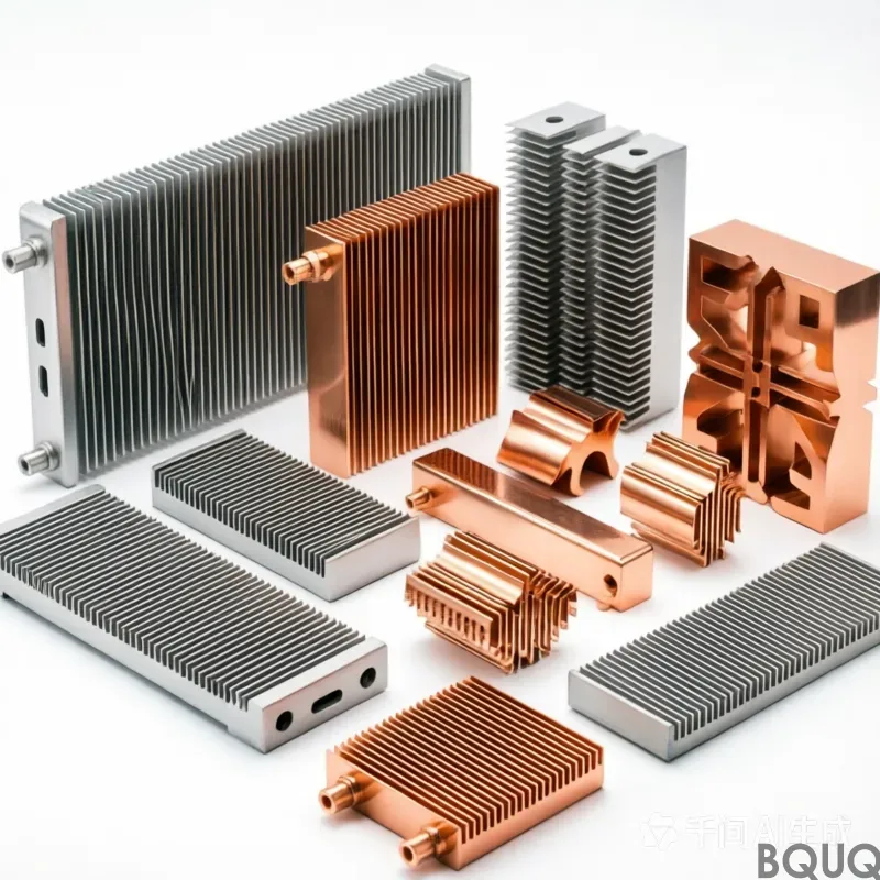
We stock both common extrusion alloys for this collection. 6063-T5 (default) offers a thermal conductivity of 201 W/m·K and a yield strength of 145 MPa, ideal for natural convection. 6061-T6 (upgrade) jumps to 276 MPa yield strength for high-vibration environments where the mounting base must also act as a structural bracket. Both alloys are fully RoHS compliant. For custom thermal loads above 150 W, we recommend our bonded-fin hybrid, but for this collection, the solid block design keeps your cost per unit under $2.80 at 500 pieces.
Mounting Base Geometry: Counterbored, Threaded, or Slotted
The "mounting base" is not a generic flat plate. Collection 02 offers three base configurations machined directly into the extrusion profile: (A) two M4 counterbored holes for through-screw attachment, (B) four M3 threaded inserts for direct PCB standoff mounting, or (C) a 10 mm wide T-slot for adjustable clamping on a test fixture. Standard base thickness is 6 mm, but we can drop to 4 mm for weight-critical designs or increase to 12 mm for heavy-duty busbar mounting. Hole positions hold true position within 0.05 mm to the part datum.
The 0.4 µm Surface Finish That Lowers Your Thermal Resistance
Rough surfaces trap air, and air is a terrible conductor. We machine the contact surface of the mounting base to a maximum Ra 0.4 µm (16 micro-inches) using a diamond-tipped finishing pass. This is not a decorative polish; it is a functional flatness that reduces thermal interface resistance by up to 18% compared to a standard milled finish of Ra 1.6 µm. If you are using a phase-change thermal pad, this finish allows the pad to wet out fully without high mounting pressure.
Straightness and Runout: Why Your Fan Won't Vibrate Loose
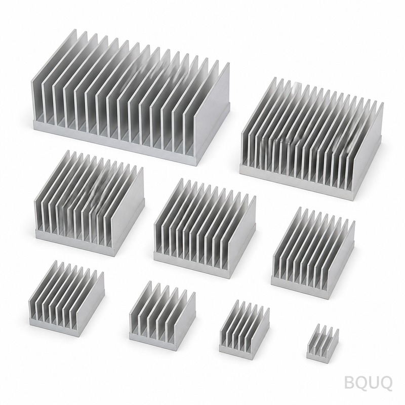
For forced-air applications, fin straightness matters. Our CNC machining centers hold fin thickness tolerance of ±0.02 mm and a straightness of 0.03 mm over the entire 50 mm fin height. The critical runout—the deviation between the mounting base datum and the outermost fin edge—is held to 0.05 mm TIR. This means your fan shroud or duct can sit within 1 mm of the fin tips without clipping, maximizing static pressure and airflow. We verify this on a Zeiss CMM for every production lot, not just first articles.
Surface Finish Options: Plain, Clear Anodized, or Black Anodized
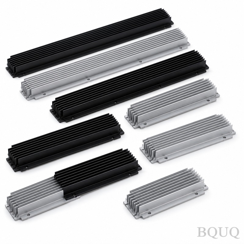
Raw machined aluminum has a natural emissivity of only 0.05, which is poor for radiative cooling. We offer three standard finishes: (1) as-machined with a chemical passivation for indoor electronics, (2) clear anodize (MIL-A-8625 Type II) at 8-12 µm thickness boosting emissivity to 0.7, and (3) black anodize with a dielectric breakdown voltage of 300 VDC, pushing emissivity to 0.9. For outdoor or wash-down environments, we recommend the black anodize as it also passes a 500-hour neutral salt spray test per ASTM B117.
In-House Testing: Flattening Check and Thermal Impedance Verification
We do not ship parts based on a single machine calibration. Every batch of Aluminum Heatsink With Mounting Base Collection 02 undergoes a 100% visual inspection for machining marks and burrs, plus a statistical flatness check on a granite surface plate. For thermal validation, we run a sample from each new die or tooling setup on our thermal test rig: a 50W power resistor clamped to the base, measuring case-to-ambient temperature rise. You receive this data sheet with your first shipment, free of charge.
Specification
Value / Range
Notes
Material
6063-T5 / 6061-T6
RoHS compliant, lead-free
Base Thickness
4 mm / 6 mm / 12 mm
Custom on request
Fin Height
25 mm – 80 mm
Standard collection range
Fin Thickness
1.5 mm – 3.0 mm
±0.02 mm tolerance
Hardness
8-12 HRC (6063) / 12-16 HRC (6061)
As-tempered
Mounting Surface Flatness
0.05 mm
Across full base area
Runout (Base to Fin Tip)
0.05 mm TIR
Verified on CMM
Contact Surface Finish
Ra 0.4 µm max
Diamond-turned finish
Lead Time
7 days (standard)
3 days for rush / 500 pcs
MOQ
No MOQ
1 piece sample available
Packing
Anti-static foam + carton
Export-grade, no damage
How to Integrate This Heatsink with Your Fastener and Mounting Hardware
Do not assume standard machine screws will work. The counterbored holes in configuration (A) are designed for a specific screw head height. If you use a socket head cap screw with a head height of 3.5 mm, the counterbore depth is exactly 3.2 mm, so the screw head protrudes 0.3 mm above the base—this is intentional for a spring washer. For configuration (B) with M3 inserts, the thread depth is 5 mm, and we recommend a minimum screw engagement of 4 full turns. If you are unsure about fastener selection, read our CNC cutting tool selection guide for guidance on thread forming versus cutting—it applies to your assembly tooling too.
Why Design Tolerances on the Base Holes Are Critical for Your Assembly Line
Our standard positional tolerance on mounting holes is 0.05 mm. But if you are using self-tapping screws into plastic housings, you may need looser tolerances to prevent cracking. Conversely, for press-fit heat spreaders, you need tighter control. We can adjust hole diameter tolerance from +0.02 / -0.00 to +0.05 / -0.05 depending on your fastener class. This flexibility is possible because we use CNC machining centers, not just extrusion dies. For a deeper understanding of what these numbers mean in practice, review our CNC machining tolerances guide—it explains the difference between positional tolerance and true position in a way most suppliers never do.
What is the minimum order quantity for this heatsink collection?
There is no MOQ—you can order a single sample for prototyping, and volume pricing kicks in at 100, 500, and 1,000 units.
Can I get a custom fin pattern or base hole layout?
Yes, we alter the fin pitch, fin height, and base hole pattern for free if you order over 50 pieces; for prototypes, there is a one-time setup fee of $40.
How do you verify the runout and flatness claim of 0.05 mm?
We use a Zeiss CMM with a 0.001 mm resolution and a calibrated granite surface plate; the measurement report is included with every batch over 100 pieces.
What is the fastest lead time for a prototype of the 6061-T6 version?
We can machine and ship a single 6061-T6 prototype within 72 hours from DXF or STEP file approval, using our in-house 5-axis CNC center.
Get a Firm Quote and DFM Feedback Within 12 Hours
Send us your 2D drawing or 3D STEP file of Aluminum Heatsink With Mounting Base Collection 02 or your custom variant. Our precision manufacturing team in Dongguan, China, will return a firm per-unit price, a DFM (Design for Manufacturing) note on any risky features, and a confirmed lead time—all within 12 business hours. We are a 20-year-old factory with 40 CNC machines, and we have exported to 30 countries. No MOQ, no hidden tooling charges for standard profiles. Email your drawing to sc@bquq.com or message us on WhatsApp at +86 13713157787 for a direct line to our senior applications engineer.