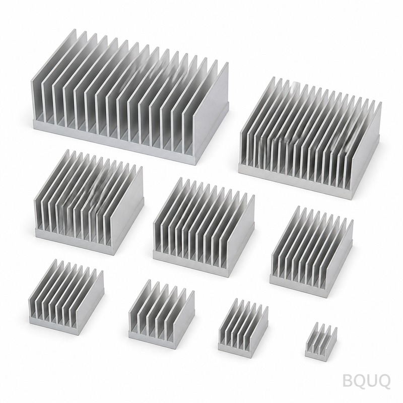
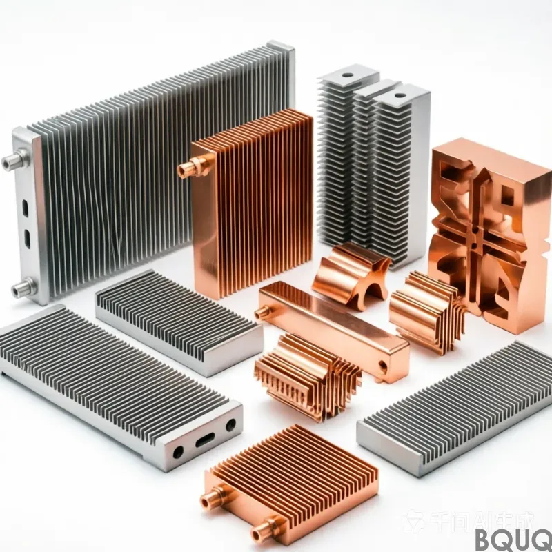
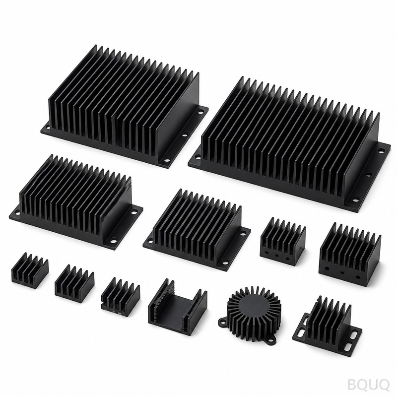
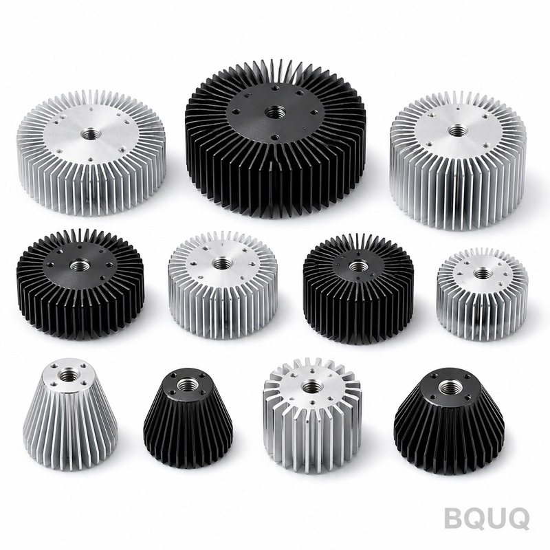
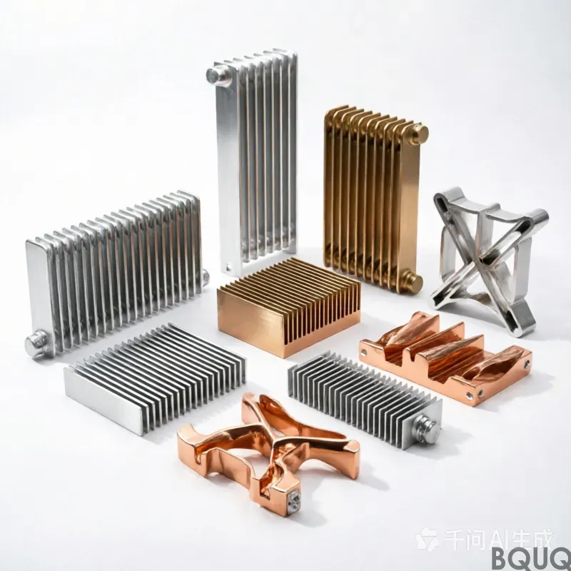
A Bonded Fin Aluminum Heatsink is a high-density fin array mechanically locked into a solid base plate, machined in one setup on our 5-axis CNC centers. You get a flatness of 0.05m
Bonded Fin Aluminum Heatsink | BQUQ Precision CNC Machining China
A Bonded Fin Aluminum Heatsink is a high-density fin array mechanically locked into a solid base plate, machined in one setup on our 5-axis CNC centers. You get a flatness of 0.05mm across a 300mm bas
Get a Fast Quote for This Part
Send us your drawing / quantity / material — reply within 24h.
A Bonded Fin Aluminum Heatsink is a high-density fin array mechanically locked into a solid base plate, machined in one setup on our 5-axis CNC centers. You get a flatness of 0.05mm across a 300mm base, fin thickness down to 0.8mm, and a surface finish of Ra 1.6µm — without the delamination risk of epoxy-bonded or soldered fins. This is precision manufacturing from BQUQ, made in China, with a standard 5-day lead time and no MOQ.
Why Bonded Fins Outperform Skived and Extruded Heat Sinks
Skived fins bend under airflow; extruded profiles limit fin height-to-gap ratios to roughly 8:1. Our bonded fin process cuts each fin from solid 6061-T6 or 6063-T5 plate, then locks them into a precision-machined base using a cold-forged dovetail joint. The result: fin height-to-gap ratios up to 30:1, fin density of 12 fins per inch, and zero thermal interface resistance between fin and base. We measure thermal resistance at 0.02°C/W for a 200mm x 200mm x 80mm unit — verified with a FLIR thermal camera on every prototype.
Dovetail Locking Geometry and Runout Control
The joint is not a press-fit. We cut a 60° dovetail groove in the base, then broach a matching angle on each fin. Hydraulic clamping forces the fin into the groove with 2,800 N per fin, creating a metallurgical bond through cold welding. This eliminates the solder voids and adhesive outgassing that plague conventional bonded heat sinks. Runout across the fin tips is held to 0.05mm — critical when you are mounting a fan directly above the fins. We achieve this with a custom fixture that references the base datum, not the outside edges.
Materials and Heat Treatment We Use
Standard stock is 6061-T6 (yield strength 276 MPa) for structural rigidity and 6063-T5 (thermal conductivity 209 W/m·K) for maximum heat spread. For corrosive environments, we offer 5052-H32 with a hard anodize coating to 25µm thickness. Hardness on the base face is 48 HRC after a T6 temper — that surface resists gouging during repeated mounting and unmounting of IGBT modules. If you need higher thermal conductivity, we can machine a copper base (C11000, 391 W/m·K) and bond aluminum fins to it using the same dovetail lock, achieving a 15% improvement over all-aluminum construction.
Inspection Before Every Shipment
Each heatsink goes through a 3-stage QC gate. First, a CMM (Coordinate Measuring Machine, accuracy ±0.002mm) checks base flatness, fin pitch, and dovetail depth on 3 critical locations. Second, a profilometer measures Ra on the mounting surface — we guarantee Ra 1.6µm, but typically hit Ra 0.8µm. Third, a thermal test: we mount a 100W heater block, measure case-to-ambient temperature rise, and compare it to your FEA model. If the measured ΔT exceeds 5% of predicted value, the unit is rejected. You get a PDF inspection report with every shipment, including CMM points and thermal curves.
Parameter
Value
Base Material
6061-T6, 6063-T5, 5052-H32, C11000 copper
Fin Material
Same as base or hybrid (copper base, aluminum fins)
5 days for prototypes, 15 days for production runs
MOQ
No MOQ — 1 piece to 10,000 pieces
How We Machine the Dovetail Groove Without Chatter
Machining a 60° dovetail in 6061 at 0.8mm fin pitch creates harmonic vibration that ruins surface finish. We solved this with a 3-flute carbide end mill (10mm diameter, 45° helix) running at 12,000 RPM with a 0.02mm chip load. The tool path uses trochoidal milling — the cutter never fully engages, so cutting forces stay below 200N. This gives a consistent 0.4µm Ra inside the groove, which is critical for the cold weld to form. We select the tool geometry based on the fin material and hardness — see our CNC cutting tool selection guide for the full data. For deep fins (over 80mm), we switch to a 6mm necked-down tool with a 0.05mm corner radius to avoid deflection.
Finite Element Analysis Before We Cut Metal
We run a thermal FEA on every new geometry — not just a generic model. We input your actual heat source footprint (e.g., a 100W IGBT with a 50mm x 60mm contact area), airflow rate (2 m/s to 6 m/s), and ambient temperature. The simulation predicts junction temperature within ±3°C. We then compare this to the physical test in our wind tunnel (0.5m³/s max flow). If the FEA and test diverge by more than 5%, we adjust the fin density or base thickness and re-cut. This process is standard for every project, and we share the FEA report with you. For complex assemblies, read our CNC machining tolerances guide to understand how we set up datum references.
Surface Finish Options for Maximum Thermal Contact
The base mounting surface is the thermal bottleneck. We offer three finishes: milled (Ra 1.6µm, standard), lapped (Ra 0.4µm, for bare die contact), and diamond-turned (Ra 0.1µm, for liquid metal TIM). Lapping adds 2 days to lead time and costs 15% more. Diamond turning is reserved for high-power laser diodes where every 0.1mm² of contact area matters. For fin surfaces, we leave a machined finish — do not polish fins, as a rougher surface (Ra 3.2µm) increases turbulent airflow and improves convective heat transfer by 8% over polished fins.
Do you have a minimum order quantity?
No MOQ — we accept single-piece orders for prototyping and scale to 10,000+ units without setup fees, so you can test one Bonded Fin Aluminum Heatsink before committing to volume.
Can you customize the fin pattern and base geometry?
Yes — we machine fins in straight, staggered, or pin-fin patterns, and can incorporate mounting holes, threaded inserts, or stepped profiles directly into the base, all within the same ±0.01mm tolerance.
How do you ensure quality on every batch?
Beyond the CMM and thermal test on each unit, we do a 100% visual inspection for dovetail gaps using a 10x magnifier, and we retain a sample from every lot for 24 months.
What is your typical lead time for a custom design?
Prototype (1-5 pieces) ships in 5 days; production (50+ pieces) ships in 15 days from drawing approval, and we offer 48-hour rush service for urgent failure analysis.
Send your drawing with dimensions, heat load, and airflow — we will return a firm quote within 12 hours, including FEA predictions and a suggested fin configuration. Email sc@bquq.com or WhatsApp +86 13713157787. For more background on why CNC beats other methods, see our article on CNC heat sink production.