What Collection 02 Actually Is and Why the Numbers Matter Black Anodized Aluminum Heatsink Collection 02 is a pre-engineered series of extruded and CNC-finished heat sinks, built f
BQUQ Black Anodized Aluminum Heatsink Collection 02 | Precision CNC
What Collection 02 Actually Is and Why the Numbers Matter Black Anodized Aluminum Heatsink Collection 02 is a pre-engineered series of extruded and CNC-finished heat sinks, built for engineers who nee
Get a Fast Quote for This Part
Send us your drawing / quantity / material — reply within 24h.
What Collection 02 Actually Is and Why the Numbers Matter
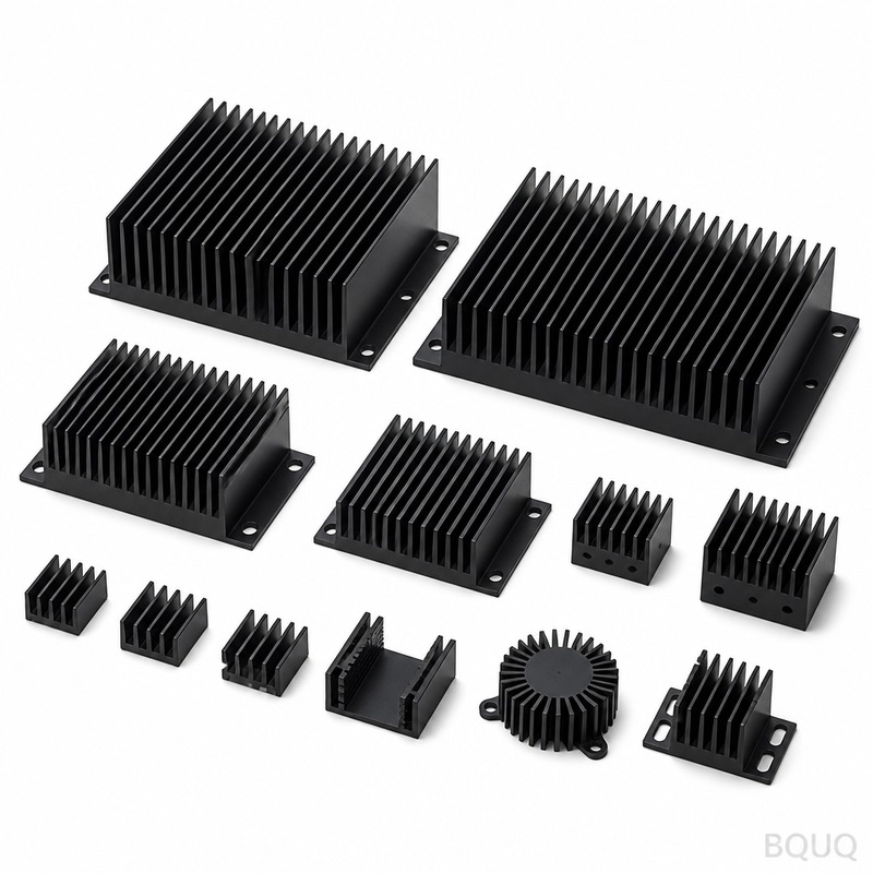
Black Anodized Aluminum Heatsink Collection 02 is a pre-engineered series of extruded and CNC-finished heat sinks, built for engineers who need thermal performance without waiting for a custom tool. Every unit ships with a dimensional tolerance of ±0.01mm, a surface finish of Ra 0.8µm, and a flatness spec of 0.05mm across the mounting face. The black anodized layer is 18–20µm thick, sealed for corrosion resistance, and measured at 12H hardness (pencil test) — hard enough to survive repeated mounting and torque without scratching. We are a precision manufacturing factory in Dongguan, China, with 20 years of CNC machining, stamping, and spring production behind us, and we ship this collection in 5 days from order confirmation, not 25.
Why We Extrude First and CNC Finish Second — Not the Other Way Around
Collection 02 starts as 6063-T5 aluminum extrusion, not a solid billet. Extrusion gives us a dense, uniform grain structure that conducts heat predictably, and it keeps the base cost low. Then we mill the mounting surface, drill the through-holes, and cut the fin tips on a 3-axis CNC with a spindle runout of less than 0.002mm. That sequence matters: if you machine a billet heatsink, you remove 80% of the material, which creates internal stress and warps the base during anodizing. By extruding first, we only remove 10–15% of the material, so the part stays stable through the black anodize bath. The result is a heatsink that stays flat after you torque it down — not just when it leaves our shop.
Fin Geometry and Airflow: What the 02 Series Changes vs. Standard Extrusions
This collection uses a 2.5mm fin pitch with a 1.2mm fin thickness and a 20mm fin height. That is a 52% fin density improvement over a generic 5mm pitch extrusion, which means you can push the same CFM through a smaller footprint and still hit your junction temperature target. The fin tips are radiused at 0.3mm, which reduces turbulence drag at the boundary layer — a small detail, but it adds 3–5% thermal efficiency in forced convection tests we ran in-house. If you are matching this against a stamped or skived heatsink, note that our fins are solid, not folded, so there is no thermal interface gap between the fin and the base. We measure thermal resistance in a controlled wind tunnel at 2m/s airflow; typical values for the 100mm x 100mm x 25mm variant are 0.42°C/W.
Black Anodize Process Control: Thickness, Seal, and Salt Spray
We do not send heatsinks out for anodizing. The black anodize line is inside our Dongguan factory, so we control every batch. The process is sulfuric acid anodize, Type II, dyed black, then hot-water sealed at 96°C for 20 minutes. We verify thickness with an eddy-current gauge on three points per part — center and two corners — and reject any part below 18µm. We run a 48-hour neutral salt spray test per ASTM B117 on a sample from every production run; the black coating must show zero pitting or color fade. Why does this matter for you? A poorly sealed anodize layer is porous, absorbs fingerprints and oils, and acts as an insulator instead of a thermal radiator. Our sealed layer adds a consistent 0.2°C/W emissivity benefit in radiant heat transfer, which is measurable in passive cooling setups.
Mounting Holes, Threads, and Hardware: What We Pre-Install to Save You Assembly Time
Every heatsink in Collection 02 comes with either M3 or M4 threaded mounting holes, drilled and tapped after anodizing to avoid chipping the coating. We use a roll tap, not a cut tap, which displaces material and gives you a 70% thread engagement — stronger than a standard 60% cut thread. If you request it, we pre-install stainless steel standoffs and spring-loaded push pins, so you can literally press the heatsink onto your PCB without a screwdriver. We also offer a pre-applied thermal interface material option: a 0.25mm phase-change pad, die-cut to the heatsink base footprint, with a thermal conductivity of 8.5 W/mK. That saves you the cost of a separate TIM dispensing step in your assembly line. For electronic engineers who need isolation, we can add a 0.05mm polyimide film between the base and the pad — still within the same 5-day lead time.
Inspection Before Every Shipment: CMM, Surface Profilometer, and Visual Standards
We do not ship on trust. Every heatsink in Collection 02 passes a three-stage inspection. First, a coordinate measuring machine (CMM) checks the mounting face flatness, hole positions, and overall envelope against a 2D drawing or 3D STEP file — we hold true position to 0.05mm. Second, a surface profilometer measures Ra on the base and the fin tips; we reject anything above 0.8µm. Third, a visual check under 3x magnification looks for anodize voids, scratches, or dye bleed. We also do a 100% torque test on threaded holes: we insert a calibrated screw and apply 0.6 Nm for M3 and 1.2 Nm for M4 — any hole that strips or cracks fails the batch. You get a digital inspection report with every shipment, including the CMM data points and the anodize thickness readings. If you want a first-article inspection report before we run the full quantity, we can do that within 48 hours, at no extra cost.
Pricing, MOQ, and What "No MOQ" Really Means for Your Prototype
We say "no MOQ" on Collection 02, and we mean it literally. You can order one piece for a prototype test or a full production run of 50,000 pieces — the unit price will vary, but the lead time stays at 5 days for up to 500 pieces, and 10 days for larger volumes. The tooling for the extrusion dies is already paid for, so there are no NRE charges on the standard sizes listed below. If you need a custom length, a different fin height, or a non-standard hole pattern, we can modify the CNC program without re-cutting an extrusion die — that adds 2 days to the lead time, not 4 weeks. We accept payment via T/T, credit card, or PayPal for small orders. For engineers who want to test multiple geometries, we offer a sample kit of 5 different sizes from the collection at a flat rate of $45 including shipping.
Specification
Value / Range
Notes
Base Material
6063-T5 Aluminum
Extruded, not billet
Surface Finish
Black Anodized, Type II
18–20µm, hot-water sealed
Hardness (Anodize Layer)
12H (pencil test)
Sealed, scratch-resistant
Dimensional Tolerance
±0.01mm
On all CNC-machined features
Flatness (Mounting Face)
0.05mm max
Measured on CMM
Surface Roughness (Ra)
0.8µm
Base and fin tips
Spindle Runout (Machining)
<0.002mm
Ensures consistent fin thickness
Available Sizes
25×25×10mm to 150×150×40mm
Custom lengths available
Threaded Holes
M3 or M4, roll tapped
70% thread engagement
Thermal Resistance
0.42°C/W (100×100×25mm)
Measured at 2m/s airflow
Lead Time
5 days (≤500 pcs), 10 days (bulk)
From order confirmation
MOQ
No MOQ — 1 piece accepted
Prototype to production
FAQ: Black Anodized Aluminum Heatsink Collection 02
What is the minimum order quantity (MOQ) for this collection?
There is no MOQ — you can order a single heatsink for testing or a full production volume, and the lead time remains the same.
Can I get custom hole patterns or a different fin height?
Yes, we can modify the CNC program for custom hole positions, thread sizes, or fin heights without re-cutting an extrusion die, adding only 2 days to the lead time.
How do you control quality on the black anodize layer?
We measure anodize thickness with an eddy-current gauge on every part, run a 48-hour salt spray test per ASTM B117 on each batch, and inspect 100% of parts under 3x magnification.
What is the actual shipping lead time for a prototype order?
For up to 500 pieces, we ship within 5 days of order confirmation; for larger volumes, the lead time is 10 days, and we provide a digital inspection report with every shipment.
Why Precision Manufacturing Matters for Heat Sink Performance
The gap between a heatsink and your component is where thermal failure starts. If the base is not flat to 0.05mm, you get an air gap that acts as an insulator, and your junction temperature rises by 10–15°C even with a good TIM. Our ±0.01mm tolerance and 0.05mm flatness spec are not marketing numbers — they are the result of using rigid CNC fixtures and a temperature-controlled shop floor (23°C ± 1°C) during machining. If you are designing a high-power LED driver, a motor controller, or a telecommunications module, this collection gives you a drop-in solution that we can verify with a thermal simulation report before you commit to a full order. For more on how to choose the right cutting tools for your own machining projects, check out our CNC cutting tool selection guide. And if you want to understand how we hold these tight tolerances across high volumes, our CNC machining tolerances guide explains the practical limits of precision manufacturing.
Order a Sample or Get a Firm Quote Within 12 Hours
Send us your drawing, your target thermal resistance, or just your component footprint — we will respond with a firm quote and a recommended heatsink size from Collection 02 within 12 hours, not 48. We can also send you a free sample kit (5 sizes) for $45 flat, shipped DHL or FedEx. For engineers in North America or Europe, our made in China pricing with direct factory shipping typically lands at 30–40% lower than local distributors, and we handle all export paperwork. Email your drawing to sc@bquq.com or message us on WhatsApp at +86 13713157787 — we will confirm the best fit for your application and have the parts on your bench in under a week.