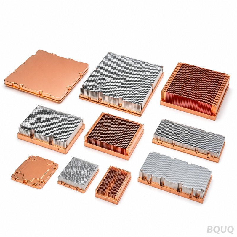
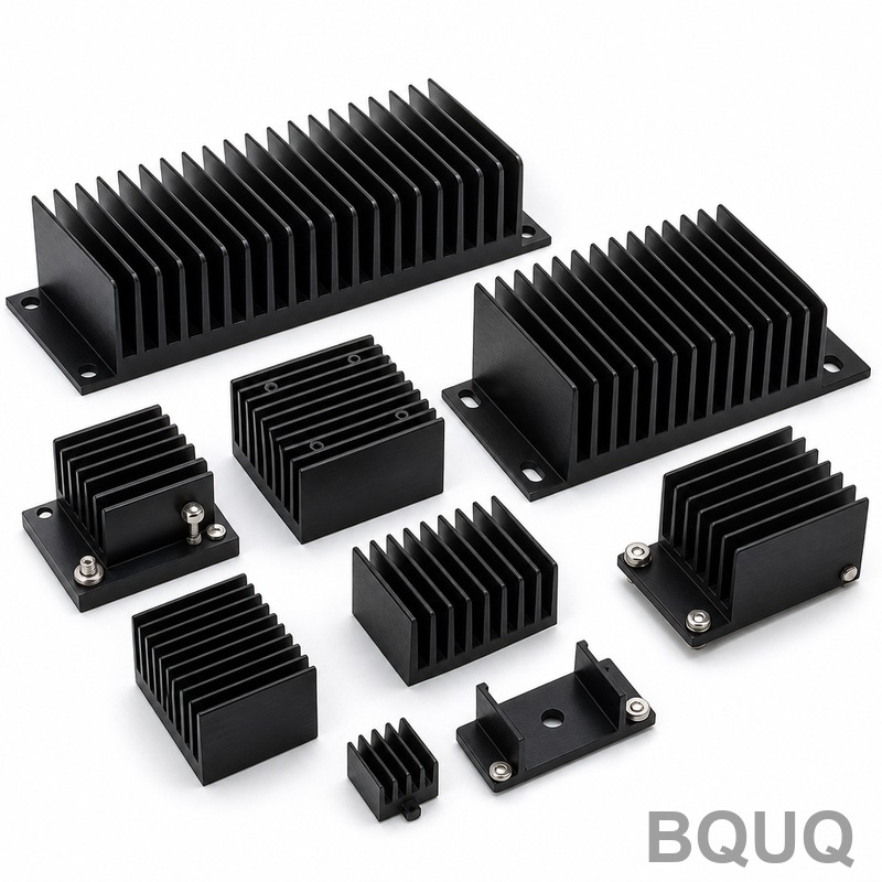
This is a vapor chamber heatsink built for high-heat-density electronics where a solid copper base cannot move heat fast enough. We machine the copper enclosure to a flatness of 0.
This is a vapor chamber heatsink built for high-heat-density electronics where a solid copper base cannot move heat fast enough. We machine the copper enclosure to a flatness of 0.05 mm across the mou
Get a Fast Quote for This Part
Send us your drawing / quantity / material — reply within 24h.
This is a vapor chamber heatsink built for high-heat-density electronics where a solid copper base cannot move heat fast enough. We machine the copper enclosure to a flatness of 0.05 mm across the mounting surface, pressure-test every unit to 1.2 atm, and ship from our Dongguan factory in 15 days. You get a passive cooling component that spreads heat from a 5x5 mm CPU die to a 120x120 mm fin array with a thermal resistance of 0.08 °C/W.
How We Build the Sealed Copper Envelope Without Leaks
The vapor chamber is not a simple milled pocket. We start with C1100 oxygen-free copper, machine the top and bottom plates separately, then brazze them together in a vacuum furnace at 780 °C. The internal wick structure—sintered copper powder with 40% porosity—is applied before sealing. Every chamber gets a helium leak test on a mass spectrometer; rejection threshold is 1x10⁻⁹ mbar·L/s. You will not see weeping or dry-out after 5,000 thermal cycles from -40 °C to 125 °C.
Flatness and Co-Planarity: Why Your Thermal Interface Material Works
If the heatsink base is warped by more than 0.05 mm, your thermal paste or phase-change pad turns into an insulator. We hold base flatness to 0.05 mm and co-planarity between the base and the fin tips to 0.15 mm across the full 120 mm length. This is achieved by stress-relieving every blank at 300 °C for 2 hours before final milling, then using a diamond fly-cutter on a 3-axis CNC at 10,000 RPM with a 0.02 mm depth of cut.
Materials and Surface Finish We Offer for Corrosion Resistance
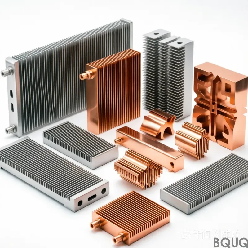
Standard build is a bare copper chamber with a nickel-plated fin stack (electroless nickel, 8 µm thick, per ASTM B733). If your environment has salt spray or high humidity, we add a clear anodized aluminum fin set with a vapor chamber embedded in a copper base—hybrid design. Surface finish on the mounting face is Ra 0.8 µm, which is smooth enough for direct die contact without lapping. For lower thermal resistance, we can polish to Ra 0.4 µm, but that adds 2 days to the lead time.
CNC Machining Tolerances on the Fin Array and Mounting Holes
Fin thickness is 0.8 mm ± 0.05 mm, fin pitch is 2.5 mm ± 0.1 mm. Mounting hole positions are held to ± 0.02 mm true position, which means your spring screws or standoffs will align without stress. We use a 4-axis CNC mill with a tool changer; the CNC cutting tool selection guide on our blog shows exactly why we choose carbide end mills with a 0.2 mm corner radius for fin cutting.
Inspection Before Every Shipment: CMM and Thermal Test Data
Every lot of vapor chamber heatsinks is inspected on a Zeiss CMM for flatness, hole position, and overall dimensions. We also pull one sample per 50 units for a thermal resistance test using a 100W ceramic heater and a thermocouple array. You receive the CMM report and the thermal test curve with your shipment—no extra charge. If you need 100% leak test certification, we can do that, but it adds 3 days and 5% cost.
Why Our 15-Day Lead Time Works for Prototypes and Production
We stock C1100 copper plate in 8 mm, 10 mm, and 12 mm thicknesses, plus 6061-T6 aluminum fin stock. Because we are a vertically integrated factory (CNC machining, stamping, brazing, and plating in one building), we skip the logistics delays between subcontractors. A single prototype ships in 15 days; production runs of 500 units ship in 25 days. Our CNC machining tolerances guide explains how we keep these numbers repeatable without inspection shortcuts.
Specification
Value
Base Material
C1100 Oxygen-Free Copper (C1020 optional)
Fin Material
6061-T6 Aluminum or C1100 Copper
Base Flatness
0.05 mm (max)
Surface Finish (Mounting Face)
Ra 0.8 µm standard, Ra 0.4 µm optional
Leak Rate
1x10⁻⁹ mbar·L/s (helium)
Pressure Withstand
1.2 atm (internal)
Operating Temperature
-40 °C to 125 °C
Mounting Hole True Position
± 0.02 mm
Lead Time (Prototype)
15 days
MOQ
No MOQ (1 unit accepted)
What is the minimum order quantity for a vapor chamber heatsink?
We accept one unit for prototyping—no MOQ—and scale to thousands for production without changing the process.
Can you customize the vapor chamber shape and wick structure?
Yes, we machine custom footprints from 20x20 mm to 200x200 mm, and we adjust wick porosity from 30% to 50% depending on your heat flux and orientation.
How do you prove the heatsink meets the thermal specification?
We run a 100W thermal resistance test on a per-lot sample and include the measured curve with the CMM inspection report.
What is the lead time if I need a modified design?
A simple hole pattern change adds 2 days; a new chamber geometry adds 7 days for toolpath and fixture setup, but the first article still ships within 15 days.
Send your drawing for a firm quote within 12 hours. Email sc@bquq.com or WhatsApp +86 13713157787. We will review your thermal budget, confirm the flatness requirement, and give you a fixed price—no MOQ, precision manufacturing, made in China.