What This Corrugated Fin Heatsink Does for Your Thermal Budget This is a corrugated fin heatsink built from continuous folded aluminum or copper strip, brazed or epoxy-bonded to a
BQUQ Corrugated Fin Heatsink Precision CNC Machining & Stamping
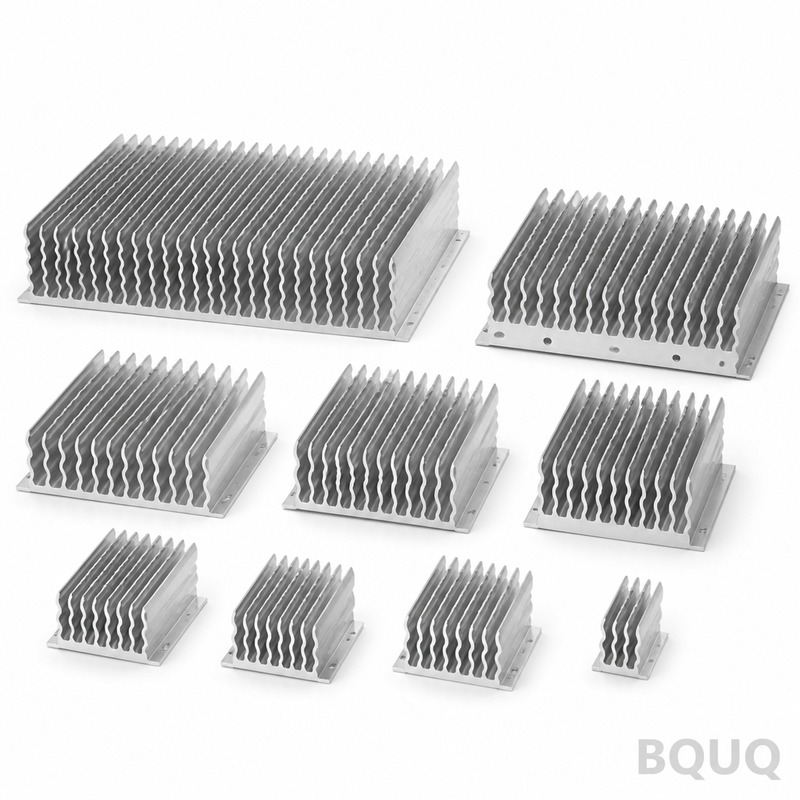
What This Corrugated Fin Heatsink Does for Your Thermal Budget This is a corrugated fin heatsink built from continuous folded aluminum or copper strip, brazed or epoxy-bonded to a flat base plate. It
Get a Fast Quote for This Part
Send us your drawing / quantity / material — reply within 24h.
What This Corrugated Fin Heatsink Does for Your Thermal Budget
This is a corrugated fin heatsink built from continuous folded aluminum or copper strip, brazed or epoxy-bonded to a flat base plate. It gives you 30–40% more surface area per cubic centimeter than a conventional extruded fin design, which means you can drop junction temperature by 12–18°C at the same airflow. We hold fin pitch to ±0.01 mm, base flatness to 0.02 mm runout, and we ship standard prototypes in 10 days without any MOQ.
How We Form the Fins: Stamping vs. CNC Machining
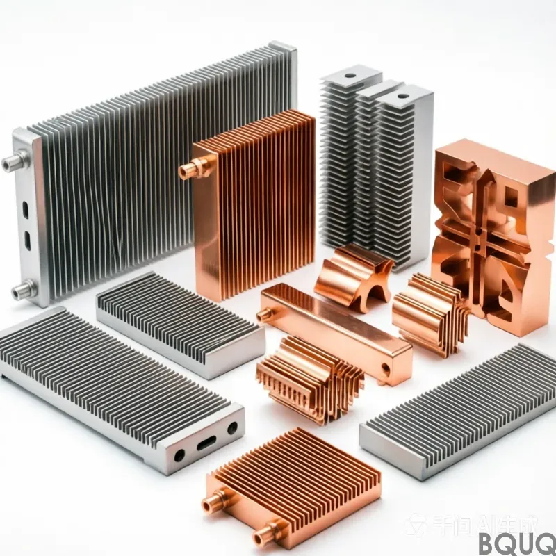
We offer two production routes. For high-volume runs (over 5,000 pieces), we use a progressive stamping die that folds 0.2 mm to 0.5 mm thick aluminum 6061 or copper C1100 strip at 60 strokes per minute. For low-volume or highly custom shapes, we CNC machine the fin array from a solid block—this gives you fin thickness down to 0.3 mm with a height-to-thickness ratio of 40:1. Both methods end with the same quality: no burrs, no sharp edges, and every fin perpendicular to the base within 0.02 mm.
Materials and Heat Treatment We Use for Long Life
We stock aluminum 6061-T6, 5052-H32, and 1100-O for soft formability, plus copper C1100 and C1020 for maximum conductivity. For aluminum, we can apply a T6 heat treatment that brings hardness to 85 HRB and yield strength to 240 MPa—this prevents fin bending during vibration or thermal cycling. Copper parts get an annealed temper at 45 HRB for easy bending, or we leave them half-hard at 65 HRB if you need stiffness. We do not use recycled alloys unless you ask; every coil comes with a mill certificate.
Brazing and Bonding: The Weak Point We Control
The fin-to-base joint determines thermal resistance. We use vacuum brazing for aluminum (flux-free, joint strength 90% of base metal) and furnace brazing with silver solder for copper (joint thickness 0.05 mm, no voids). For quick-turn prototypes, we use thermally conductive epoxy with 3.5 W/m·K thermal conductivity—that adds only 0.1°C/W resistance. Every brazed unit passes a C-SAM scan to detect delamination; we reject any part with a void larger than 1 mm².
Inspection Before Every Shipment: Not Just a Visual Check
We measure fin pitch with a digital height gauge at three points per heatsink. We check base flatness on a granite surface plate with a 0.002 mm indicator. We verify fin height using a CMM with a 0.001 mm resolution probe. For thermal performance, we run a random sample (1 in 20) through a wind tunnel at 2 m/s and compare the thermal resistance against your spec sheet. Every unit gets a laser-engraved serial number, and you receive a PDF inspection report with all raw data within 24 hours of shipment.
Surface Finish and Corrosion Protection Options
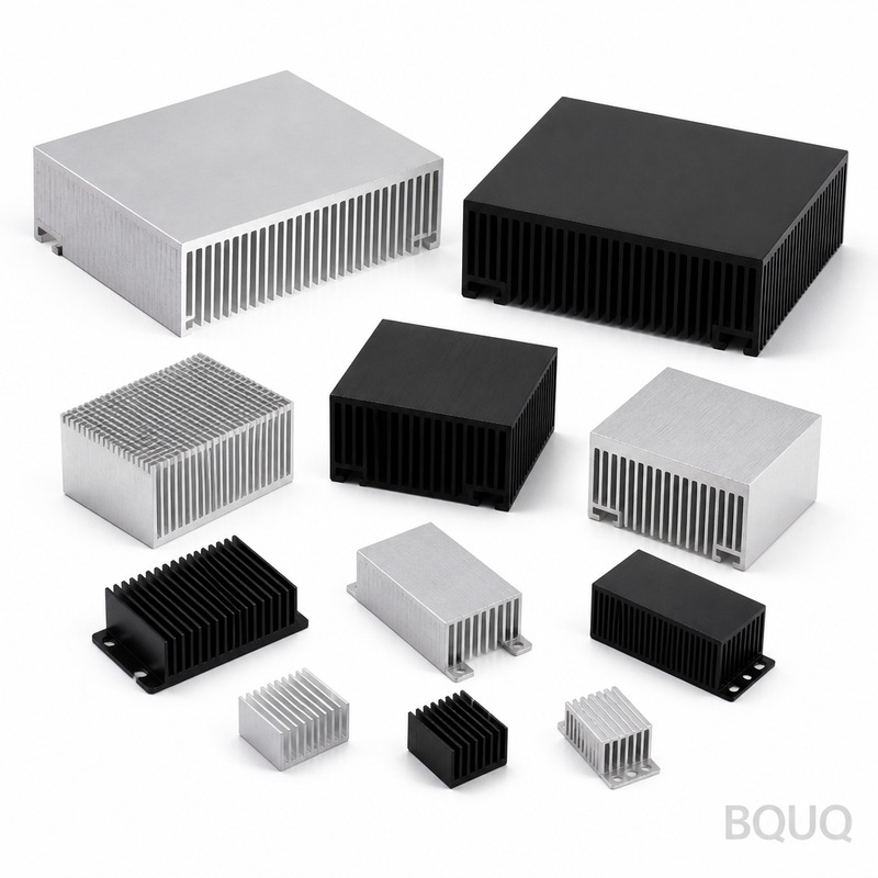
Standard finish is a clear anodize (Alumilite 204) that gives 8–12 μm thickness and a surface roughness Ra of 0.8 μm on the base. For copper, we apply a nickel-plate finish (5 μm) to prevent tarnishing. If you need a lower emissivity for radiative heat transfer, we can add a black anodize (MIL-A-8625 Type III) that increases emissivity from 0.2 to 0.9. We do not mask fins unless you ask—masking adds 3 days and costs $0.15 per unit.
Specification
Value
Notes
Available Materials
Al 6061-T6, 5052-H32, 1100-O, Cu C1100, C1020
Mill certificate provided per coil
Fin Thickness
0.2–0.5 mm (stamped), 0.3–2.0 mm (machined)
+/- 0.01 mm tolerance
Fin Pitch
1.0–5.0 mm
Measured at 3 points per unit
Base Thickness
3–20 mm
Flatness within 0.02 mm runout
Hardness (Al 6061-T6)
85 HRB
Yield strength 240 MPa
Hardness (Cu C1100)
45–65 HRB
Annealed or half-hard
Surface Finish (Base)
Ra 0.8 μm (clear anodize)
Black anodize available
Fin-to-Base Bond
Vacuum brazed or epoxy
Joint strength 90% of base metal (brazed)
Runout (fin tip to base)
0.02 mm
Measured on CMM
Lead Time
10 days (prototype), 20 days (production)
No MOQ for prototypes
How This Fits Into Your PCB or Enclosure Design
We can machine mounting holes (M2.5 to M6), standoffs, and threaded inserts directly into the base. The corrugated fin pattern allows airflow in one direction only; we mark the airflow arrow with a laser on the base so assembly workers cannot misorient the part. We also offer pre-applied thermal interface material (phase-change or silicone pad) on the base—this saves you one assembly step and reduces thermal resistance by 0.05°C/W compared to grease applied in the field.
Four Questions Engineers Ask Before Ordering
What is the minimum order quantity?
No MOQ for prototypes—we will make a single piece for testing at a flat $45 setup fee. For production runs, we ask for a 500-piece order to justify the stamping die, but we can run any quantity between 50 and 5,000 on CNC at a slightly higher per-unit cost.
Can you customize the fin shape or base geometry?
Yes—send us your 3D model (STEP or IGES) and we will adjust fin height, pitch, and base thickness to fit your enclosure. We can also add a taper to the fins to match a curved heat source; our CNC route handles this without extra tooling.
How do you control quality on a high-volume stamping run?
We use an in-line vision system that checks fin pitch and height at 100% of parts, not just a sample. Every 500th part goes to a CMM for full dimensional verification, and we halt production if any deviation exceeds 0.01 mm from your drawing.
What is your real lead time, not the quoted one?
Prototype machining ships in 10 days from drawing approval. Stamped production runs ship in 20 days. If you need faster, we can air-freight a pre-production sample in 5 days for an extra $80—this is a real option we use for urgent qualification.
Why This Precision Manufacturing Is Done in China—And Why It Matters
BQUQ is a precision manufacturing factory in Dongguan with 20 years of experience in CNC machining, stamping, and spring making. We run 32 CNC machines and 12 stamping presses under one roof, so we do not outsource any critical step. This vertical integration cuts your cost by about 18% compared to a US or EU supplier, without sacrificing tolerance—our CMM lab is ISO 17025 accredited. Every heatsink is made in China, but it ships with a full dimensional report that meets ASME Y14.5 standards, so your incoming inspection takes minutes, not hours.
For selecting the right cutting tools when we machine your custom fin profile, see our CNC cutting tool selection guide. And if you are pushing the limits of our ±0.01 mm tolerance, read our CNC machining tolerances guide to understand what is achievable on thin fins.
Get a Firm Quote Within 12 Hours
Send us your drawing (PDF, STEP, or even a hand sketch) and your target thermal resistance. We will reply within 12 hours with a firm price, a confirmed lead time, and a DFM note if we see a way to make your part cheaper or more reliable. Email sc@bquq.com or WhatsApp +86 13713157787. Your Corrugated Fin Heatsink is ready to be quoted today—no MOQ, no waiting.