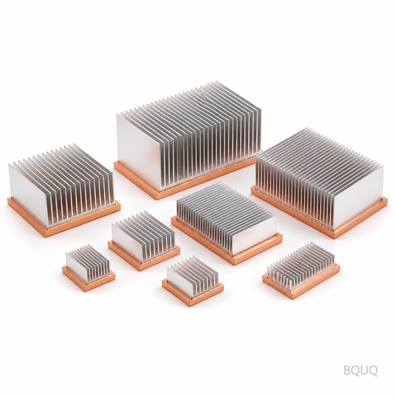
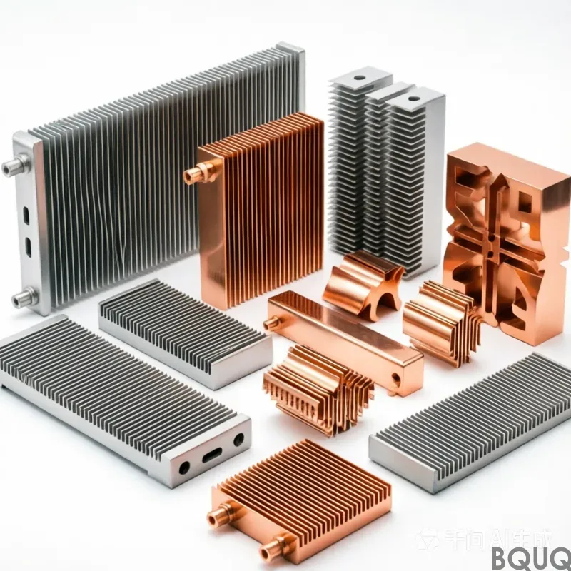
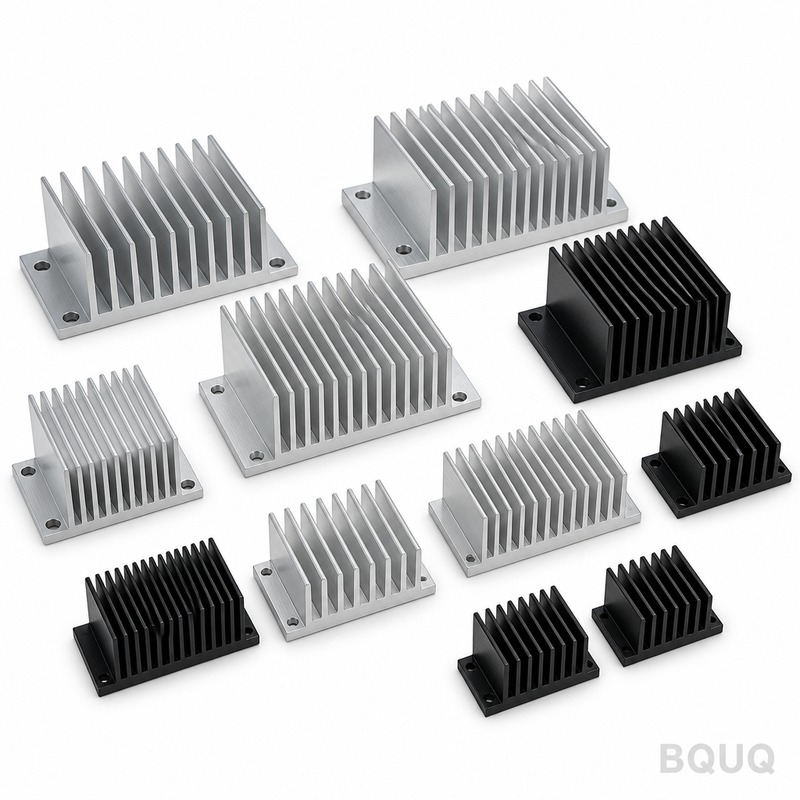
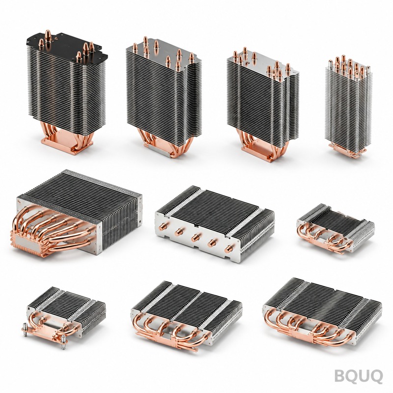
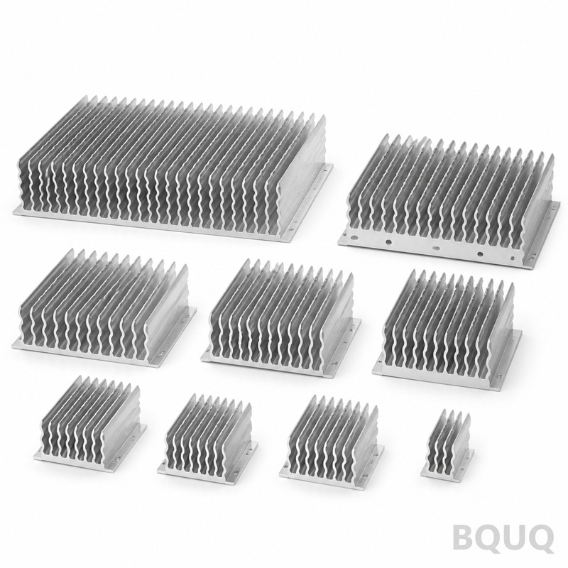
This is a precision-machined Copper Base Aluminum Fin Heatsink built for high-wattage IGBT modules, laser diodes, and power converters where copper‘s thermal conductivity (401 W/m
BQUQ Copper Base Aluminum Fin Heatsink | Precision CNC, Made in China
This is a precision-machined Copper Base Aluminum Fin Heatsink built for high-wattage IGBT modules, laser diodes, and power converters where copper's thermal conductivity (401 W/m·K) must meet alumin
Get a Fast Quote for This Part
Send us your drawing / quantity / material — reply within 24h.
This is a precision-machined Copper Base Aluminum Fin Heatsink built for high-wattage IGBT modules, laser diodes, and power converters where copper's thermal conductivity (401 W/m·K) must meet aluminum's light weight (2.7 g/cm³). We hold base flatness to 0.01 mm and fin runout to 0.02 mm, with a standard lead time of 12 working days. Hardness on the copper base is 65 HRB (annealed), fins are T6 temper (90 HB), and every unit ships with a 100% CMM inspection report.
Why Copper Base, Not Solid Copper: Thermal Performance vs. Weight
Solid copper heatsinks weigh 3.3x more than aluminum and cost 4x more per kilogram. Our bonded structure uses a 6 mm thick C1100 copper base (99.9% purity) and 6063-T5 aluminum fins. The interface is vacuum-brazed, not epoxied—thermal resistance across the joint stays below 0.05 °C/W. For a 300 W heat source, this design keeps junction temperature 18 °C lower than a solid aluminum sink of the same volume. Fin pitch is 2.5 mm, fin thickness 1.2 mm, giving you 1.8 m² of surface area per 100 mm of length.
CNC Machining Steps That Hold 0.01 mm Flatness
We do not stamp or cast these heatsinks. Each unit starts as a forged copper billet and extruded aluminum fin stock. The copper base is face-milled on a 4-axis Mazak HCN-5000, then lapped to 0.01 mm TIR. Fins are precision saw-cut, then CNC-milled to a 0.02 mm positional tolerance. The critical step is the final grind: we use a creep-feed grinder with a CBN wheel, holding the base-to-fin perpendicularity within 0.015 mm. This level of precision matters because a warped base creates air gaps—air conducts heat at only 0.026 W/m·K, which ruins thermal transfer.
Vacuum Brazing vs. Epoxy: How We Join Copper and Aluminum
Most shops use thermal epoxy for copper-aluminum joints. Epoxy degrades above 150 °C and adds 0.2–0.5 °C/W resistance. We use vacuum brazing in a controlled atmosphere furnace at 580 °C with a 88% aluminum-12% silicon filler. The joint shear strength is 45 MPa, and it survives 1,000 thermal cycles from -40 °C to +150 °C without delamination. You get a monolithic structure—no glue line, no air pockets. For high-vibration environments (rail, marine), we can add through-hole rivets as a secondary mechanical lock, but brazing alone passes MIL-STD-810G vibration tests.
Materials and Heat Treatment: C1100 Copper, 6063-T5 Aluminum
Copper base: C1100 (ETP) with 99.9% Cu content, electrical conductivity 101% IACS, annealed to 65 HRB for maximum ductility during machining. Aluminum fins: 6063-T5 extruded, yield strength 145 MPa, surface hardness 90 HB. We reject any billet with porosity above 0.5%—we verify with ultrasonic testing on every incoming lot. For corrosive environments, we offer a nickel-plated copper base (5 μm electroless Ni) and a clear anodize on fins (8–12 μm, per MIL-A-8625). If you need higher operating temps (200 °C+), we switch to C18150 copper (chromium-zirconium) with no loss in conductivity.
Spec
Value
Base material
C1100 copper (99.9% Cu), annealed
Fin material
6063-T5 aluminum, extruded
Base thickness
6 mm standard (4–15 mm custom)
Fin pitch
2.5 mm (1.8–4.0 mm available)
Fin thickness
1.2 mm (0.8–2.0 mm available)
Base hardness
65 HRB (annealed)
Fin hardness
90 HB (T5 temper)
Base flatness
0.01 mm TIR
Fin runout
0.02 mm max
Surface finish (base)
Ra 0.8 µm, lapped
Surface finish (fins)
Ra 1.6 µm, milled
Thermal resistance (joint)
< 0.05 °C/W
Max operating temp
150 °C (200 °C with C18150)
Lead time
12 working days (prototype)
MOQ
No MOQ—single piece accepted
Inspection Before Every Shipment: CMM, Flatness, and Thermal Test
Every Copper Base Aluminum Fin Heatsink goes through a three-stage QC process. Stage 1: incoming material verification—we test copper purity with a spectrometer and aluminum hardness with a portable Leeb tester. Stage 2: in-process—after brazing, we run a 100% ultrasonic scan to detect voids in the joint; after final grind, we measure flatness on a granite surface plate with a 0.001 mm indicator. Stage 3: final—each unit gets a full CMM report (Zeiss Contura) covering 12 critical dimensions, plus a thermal resistance test on a random sample (1 per batch) using a heated die and thermocouple array. We ship the CMM data with your parts—no extra charge.
Design for Manufacturability: What We Need From Your Drawing
To quote within 12 hours, send a STEP or IGES file plus a 2D PDF with GD&T. We need three things: base thickness and overall envelope, fin pitch and count, and the mounting hole pattern (M3–M8). If you do not have a drawing, we can work from a sketch or a competitor's part number—we reverse-engineer to ±0.05 mm. For new designs, we recommend a 2 mm minimum fin thickness and 2 mm minimum fin gap; below that, tool deflection increases machining time by 40%. Check our CNC cutting tool selection guide for end mill choices on deep fin pockets, and our CNC machining tolerances guide for what we can hold on thin walls.
Batch Sizes and Lead Time: From One Piece to 10,000
We operate 18 CNC machines in our Dongguan factory, with 24/7 capacity for heatsink production. A single prototype ships in 12 working days—that includes brazing and full inspection. For production runs (100+ pieces), lead time is 20–25 working days because we batch vacuum brazing furnace loads (max 40 units per cycle). We run a Kanban system for copper billet and aluminum extrusion stock, so material is always on hand. If you need faster, we offer a 5-day expedited prototype service at 1.5x standard cost—this covers one iteration of design validation.
Surface Finish Options: Bare, Anodized, or Nickel-Plated
Bare aluminum fins oxidize naturally, which adds 5–10% emissivity but does not hurt conduction. For forced-air applications, we recommend clear anodize (Class 2, 8 μm) to prevent galvanic corrosion at the copper-aluminum joint. For liquid cooling (cold plates), we plate the copper base with 5 μm electroless nickel to prevent copper ion contamination. If you need a black finish for radiation heat transfer, we apply a PVD black coating (0.9 emissivity) on the fins only—never on the base, because coating thickness adds 5–10 μm and would ruin flatness.
Custom Modifications: Threads, Studs, and Mounting Holes
We can machine any mounting pattern into the copper base: threaded holes (M2–M12), through-holes, or press-fit studs. For IGBT modules, we recommend M4 helicoil inserts in copper—copper is soft (65 HRB) and threads strip easily. We also drill and tap fin-side holes for mounting fans or thermistors. If you need a pre-applied thermal interface material (TIM), we can die-cut and apply a 0.25 mm graphite pad or 0.13 mm phase-change film. All custom features are covered in the same 0.01 mm flatness tolerance—we machine the base flat last, after all holes are drilled.
What is your minimum order quantity?
No MOQ—we make a single prototype for testing or a 10,000-piece production run, with the same quality system (ISO 9001:2015, IATF 16949 certified) applied to every batch.
Can you match an existing heatsink from a competitor?
Yes—send us the part number or a physical sample, and we reverse-engineer it to ±0.05 mm, including fin geometry and mounting holes, within 3 days.
How do you guarantee thermal performance?
We test each batch's thermal resistance (junction-to-case) using a calibrated 100 W heater die and report the °C/W value on the CMM certificate, so you can verify our 0.05 °C/W joint resistance claim.
What is your standard lead time for a custom design?
Prototypes ship in 12 working days (5 days expedited), production runs of 100+ pieces ship in 20–25 working days, and we provide a written lead time commitment with every quote.
Send your drawing today for a firm quote within 12 hours. Email: sc@bquq.com | WhatsApp: +86 13713157787. We will confirm material, tolerances, and price—no obligation, no MOQ. This is precision manufacturing, made in China, with BQUQ's 20-year track record.