Achieving Optical Surface Quality with CNC Machining Guide
Introduction to Optical Surface Quality in CNC Machining
In the world of precision manufacturing, achieving optical surface quality—often defined as surface roughness below 10 nm Ra—is the holy grail for components used in lasers, aerospace optics, medical devices, and high-end consumer electronics. While traditionally associated with grinding and polishing, modern CNC machining centers equipped with advanced tooling and control systems can now deliver mirror-like finishes straight from the cutting tool. This guide explores the techniques, parameters, and best practices necessary to transform standard CNC lathes and mills into optical-grade finishing machines.
What Is Optical Surface Quality?
Optical surface quality refers to a surface that reflects and transmits light with minimal scattering or distortion. Quantitatively, it is characterized by:
Surface Roughness (Ra): Typically below 10 nm for optical applications.
Form Accuracy: Deviation from the intended shape (e.g., flatness, curvature) often required to be < 0.5 μm.
Subsurface Damage: Minimal micro-cracks or residual stresses that can degrade performance.
While CNC machining alone may not achieve the absolute smoothest surfaces (that often requires post-polishing), it can dramatically reduce the need for manual finishing, saving time and cost.
Key Factors for Optical Surface Quality in CNC
Machine Rigidity and Vibration Control
For optical finishes, the machine tool must be exceptionally rigid. Any vibration—from spindle imbalance, floor vibrations, or cutting forces—will imprint onto the workpiece surface. Use vibration-dampening mounts, active vibration control systems, and design fixtures that maximize stiffness. High-end machines with hydrostatic or air bearings are preferred.
Spindle Precision and Speed
Spindle runout should be less than 1 μm. For diamond turning, speeds often exceed 10,000 RPM with extremely low thermal growth. Precision angular contact bearings or magnetic spindles are common.
Cutting Tool Geometry and Material
Single-crystal diamond tools are essential for non-ferrous materials (aluminum, copper, plastics) when targeting optical finishes. For ferrous metals, like steel, cubic boron nitride (CBN) or fine-grained carbide with specialized coatings (e.g., diamond-like carbon) are used. Tool nose radius is critical: larger radii (0.5-2 mm) yield lower roughness but require careful control of feed rate.
Feed Rate and Depth of Cut
To achieve optical finishes, feed rates must be very low—typically 0.001-0.01 mm/rev (1-10 μm/rev). The theoretical roughness is given by: Ra ≈ (f^2) / (32 × r), where f is feed per revolution and r is tool nose radius. For Ra = 10 nm, with a 1 mm nose radius, feed must be ~0.006 mm/rev. Depth of cut in finishing passes is often 10-50 μm, ensuring the tool cuts in the ductile regime.
Techniques for Optical Surface Machining
Single-Point Diamond Turning (SPDT)
SPDT uses a natural or synthetic diamond tool on a precision lathe. It is ideal for symmetric components like lenses, mirrors, and part geometries that can be rotated. Modern SPDT machines achieve sub-nanometer roughness.
Ultra-Precision Milling
For freeform optics or non-rotationally symmetric parts, ultra-precision milling with diamond ball end mills is employed. The tool paths are generated using CAM software that accounts for scallop height and constant engagement.
Micro-Machining and High-Frequency Vibration-Assisted Machining
Ultrasonic vibration (20-40 kHz) applied to the cutting tool or workpiece reduces cutting forces, suppresses burr formation, and allows machining of brittle materials (glass, ceramics) in the ductile mode, yielding optical surfaces without fracture.
Post-Process Integration
For the highest quality, CNC machining often serves as a pre-polishing step. After machining, a short magnetorheological finishing (MRF) or polishing step can remove remaining tool marks to bring roughness below 1 nm.
Materials and Their Machinability to Optical Quality
| Material | Ease of Achieving Optical Finish via CNC | Recommended Tool |
|---|---|---|
| Aluminum (6061, 7075) | Excellent | Diamond |
| Copper (OFHC) | Excellent | Diamond |
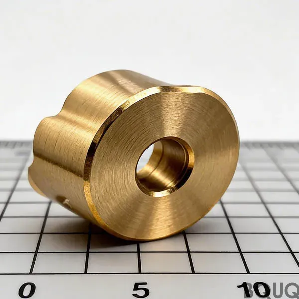
| Brass | Good | Diamond or carbide |
| Stainless Steel (304, 316) | Moderate | CBN or carbide (diamond not recommended due to chemical affinity) |
| Titanium | Challenging | Carbide with special coatings |
| Plastics (acrylic, polycarbonate) | Excellent | Diamond |
| Ceramics (alumina, silicon carbide) | Difficult, requires ultrasonic assistance | Diamond |
Inspection Methods for Optical Surfaces
Verifying optical quality requires specialized metrology:
White Light Interferometry: Provides 3D surface topography with nm resolution.
Atomic Force Microscopy (AFM): for nanoscale roughness measurement.
Phase Shifting Interferometry: for form accuracy.
Profilometry (stylus or laser): for roughness profiles.
Reflectivity and Haze Measurements: to quantify scattering.
In-process monitoring using acoustic emission or force sensors can help detect deterioration before surface quality degrades.
Practical Tips for Achieving Optical Quality on Conventional CNC Machines
Not everyone has an ultra-precision lathe. Here are tips to improve surface finish on standard equipment:
Use a wiper insert: These have a special geometry that smears the surface, reducing roughness.
Reduce vibration: Use machine feet, avoid unbalanced tools, and consider a dynamic balancing setup.
Optimile cutting parameters: Use high spindle speed with low feed and shallow depth of cut. Test a range to find the sweet spot.
Apply high-pressure coolant: This evacuates chips and reduces built-up edge.
Use a finishing pass with a new insert: Even a slight edge wear increases roughness.
Consider climb milling: It provides better finish than conventional milling in most materials.
Case Study: CNC Machining of an Aluminum Mirror for a Telescopic System
A customer required an aluminum parabolic mirror with surface roughness < 10 nm Ra and form error < 1 μm. Using a diamond-turning lathe with a single-crystal diamond tool (nose radius 1.5 mm), the following parameters were used: spindle speed 4000 RPM, feed 0.005 mm/rev, depth of cut 10 μm. After machining, the surface roughness measured 8 nm Ra. The mirror was then lightly polished (MRF) to 2 nm Ra. The process eliminated downstream grinding steps, reducing lead time by 40%.
Conclusion: The Future of Optical Surface Quality in CNC Machining
Achieving optical surface quality with CNC machining is no longer a niche capability reserved for specialized labs. With careful machine selection, proper tooling, and optimized parameters, even conventional CNC shops can produce components that meet stringent optical standards. By integrating advanced techniques like ultrasonic vibration assistance and real-time metrology, the gap between machining and polishing continues to narrow. For manufacturers looking to offer high-value precision parts, investing in optical finishing capabilities provides a clear competitive advantage.
Frequently Asked Questions
Can CNC machining really achieve optical surface quality, or is polishing always required?
Modern CNC machining can achieve optical surface quality, defined as surface roughness below 10 nm Ra, directly from the cutting tool. While it may not always match the absolute smoothest surfaces from post-polishing, it dramatically reduces the need for manual finishing, saving time and cost.
What are the key machine requirements for optical-grade CNC finishes?
The machine must be exceptionally rigid with vibration-dampening mounts or active vibration control. Spindle runout should be less than 1 μm, and speeds often exceed 10,000 RPM. High-end machines with hydrostatic or air bearings are preferred to prevent vibration from imprinting on the workpiece.
What cutting tools and parameters are needed for a 10 nm Ra finish?
Use single-crystal diamond tools for non-ferrous materials, or CBN/fine-grained carbide with coatings for ferrous metals. Tool nose radius should be 0.5-2 mm. Feed rates must be 0.001-0.01 mm/rev; for Ra = 10 nm with a 1 mm nose radius, feed must be ~0.006 mm/rev. Finishing depth of cut is typically 10-50 μm.
What quantitative specifications define optical surface quality in CNC parts?
Optical surface quality requires surface roughness below 10 nm Ra, form accuracy deviation less than 0.5 μm, and minimal subsurface damage such as micro-cracks or residual stresses. These specifications ensure minimal light scattering or distortion for applications like lasers, aerospace optics, and medical devices.