
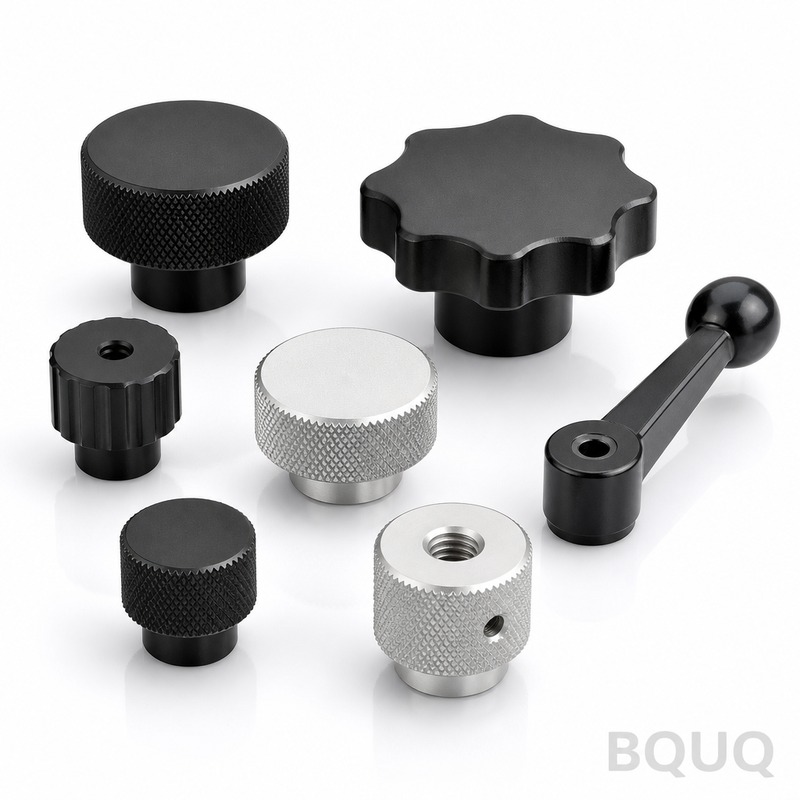
CNC Machining Aluminum Speeds Feeds and Best Practices for Precision Parts
CNC machining aluminum is a high-speed, high-efficiency process, but optimal parameters depend entirely on the alloy, tool geometry, and machine rigidity. For 6061-T6, a common starting point is 800-1200 SFM (surface feet per minute) with a chip load of 0.002-0.005 inches per tooth, while 7075-T6 requires a 20% reduction in speed to manage heat. This article provides the exact spindle speeds, feed rates, and operational guidelines to achieve tight tolerances of +/- 0.005 mm and superior surface finishes in your production runs.
Material Selection and Its Impact on Speeds
Aluminum is not a single material when it comes to machining. The alloy choice dictates the cutting parameters because of differences in hardness, thermal conductivity, and chip formation. At BQUQ, we classify aluminum into three machining categories.
Wrought alloys like 6061-T6 and 6082-T6 are the most common for CNC machining due to their excellent strength-to-weight ratio and predictable chip breaking. These alloys machine best at higher speeds. Cast alloys such as A380 and ADC12 contain silicon, which is abrasive and requires lower speeds but offers excellent dimensional stability for high-volume parts. High-strength alloys like 7075-T6 and 2024-T4 are harder and generate more heat; they demand reduced speeds and increased coolant flow to prevent work hardening.
For 6061-T6, thermal conductivity is approximately 167 W/m-K, which allows heat to dissipate quickly from the cutting zone. This permits speeds up to 1,200 SFM with carbide tooling. In contrast, 7075-T6 has a thermal conductivity of about 130 W/m-K, necessitating a speed reduction to 900 SFM to avoid burning the material or causing built-up edge.
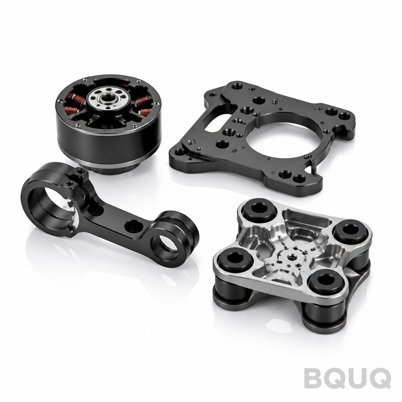
Optimal Spindle Speed and Feed Rate Calculations
The formula for spindle speed is RPM = (SFM x 3.82) / Tool Diameter. For a 1/4-inch end mill cutting 6061-T6 at 1,000 SFM, the calculation is: RPM = (1000 x 3.82) / 0.25 = 15,280 RPM. Most production CNC machines run between 10,000 and 15,000 RPM, which is ideal for aluminum.
Feed rate is calculated as: Feed (IPM) = RPM x Number of Flutes x Chip Load. Using the above RPM of 15,280 with a 2-flute end mill and a chip load of 0.004 inches per tooth, the feed rate is 15,280 x 2 x 0.004 = 122 inches per minute. This aggressive feed rate is effective because aluminum chips are ductile; a thicker chip removes the heat from the cut zone, preventing it from transferring into the tool and workpiece.
For finishing passes, reduce the chip load to 0.0015-0.002 inches per tooth and increase the speed by 10%. This produces a surface finish of 16-32 Ra microinches. For roughing, use a chip load of 0.005-0.007 inches per tooth to maximize material removal rate. The radial depth of cut should be 40-50% of tool diameter for roughing and 5-10% for finishing.
Tooling Geometry and Coating Selection
Tool geometry is the primary factor in preventing chip welding in aluminum. Standard high-speed steel (HSS) tools are obsolete for production aluminum. We recommend solid carbide end mills with a polished flute finish and an unequal helix angle. A 45-degree helix angle provides better shearing action and reduces cutting forces, while a variable helix design minimizes vibration and chatter at high RPM.
Coating selection is critical. Titanium Nitride (TiN) is not recommended for aluminum due to its affinity for the metal. Instead, use uncoated carbide for general machining or tools with a Titanium Diboride (TiB2) coating. TiB2 has a hardness of 3,400 Vickers and a low coefficient of friction, specifically designed to prevent aluminum from adhering to the cutting edge.
A 3-flute end mill is often superior to a 2-flute for aluminum. Three flutes provide a larger core diameter for rigidity while still offering sufficient chip clearance. For example, a 3-flute, 1/2-inch end mill can run at 4,000 RPM with a feed rate of 60 IPM and a 0.050-inch radial depth of cut. The larger core reduces deflection by 30% compared to a 2-flute design, enabling tighter tolerance machining.
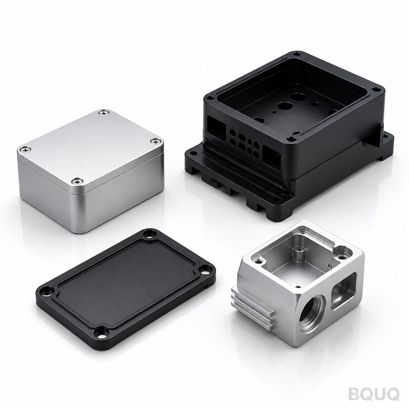
Cooling and Lubrication Strategies
Aluminum has a low melting point of 660 degrees Celsius, but the issue is not melting; it is the thermal expansion. Aluminum expands at 23.6 x 10^-6 per degree Celsius. If the part heats up by 50 degrees Celsius during machining, a 100 mm part will grow by 0.118 mm, exceeding most tolerance requirements. Therefore, temperature control is non-negotiable.
Flood coolant is the standard for aluminum machining, using a water-soluble emulsion at 8-10% concentration. The coolant serves two purposes: lubricating the cutting zone and flushing chips. A minimum flow rate of 5 gallons per minute per horsepower is required. For high-speed machining above 12,000 RPM, through-spindle coolant at 300-1,000 PSI is recommended to ensure coolant reaches the cutting edge and to break chips hydraulically.
Minimum Quantity Lubrication (MQL) or mist cooling is an option for finishing operations, but it is not suitable for deep pocketing due to inadequate chip evacuation. In dry machining, compressed air at 80-100 PSI can be used, but this is only viable for very light cuts. At BQUQ, we maintain a coolant temperature of 25 degrees Celsius using a chiller to ensure consistent part dimensions across long production runs.
Common Defects and Troubleshooting
Built-up edge (BUE) is the most common defect in aluminum machining. It occurs when aluminum welds to the cutting edge, causing poor surface finish and dimensional inaccuracy. The solution is to increase the cutting speed by 15-20% to generate enough heat to soften the chip, or to use a sharper edge geometry with a positive rake angle.
Chatter is another frequent issue, often caused by tool deflection or insufficient rigidity. The fix is to reduce the tool overhang (length-to-diameter ratio should be less than 4:1) or increase the feed rate to move into a stable cutting zone. If the part is moving, use a stronger workholding method. A vacuum fixture or a custom soft jaw with serrated inserts can increase holding force by 40% compared to standard vises.
Surface tearing indicates that the tool is dull or the chip load is too light, causing rubbing instead of cutting. Increase the feed rate or replace the insert. If you see excessive burr formation on the edges, the tool geometry is incorrect; use a tool with a sharper corner radius (0.010-0.020 inches) to minimize burrs.
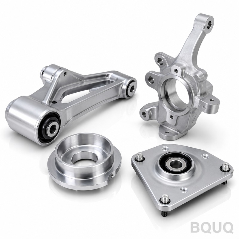
Data Table: Recommended Parameters for Common Alloys
| Alloy | Spindle Speed (SFM) | Chip Load (in/tooth) | Feed Rate (IPM for 1/4" 2-flute) | Coolant Pressure (PSI) | Typical Tolerance (mm) | Surface Finish (Ra) |
| 6061-T6 | 1000-1200 | 0.003-0.005 | 90-122 | 100-300 | +/- 0.005 | 16-32 |
| 7075-T6 | 800-900 | 0.002-0.004 | 60-80 | 200-400 | +/- 0.008 | 32-63 |
| 2024-T4 | 700-800 | 0.002-0.003 | 50-60 | 150-300 | +/- 0.010 | 32-63 |
| A380 Cast | 600-700 | 0.003-0.005 | 60-80 | 100-200 | +/- 0.013 | 63-125 |
| 6082-T6 | 1000-1100 | 0.003-0.005 | 80-110 | 100-300 | +/- 0.005 | 16-32 |
Cost Optimization and Lead Time Considerations
The cost of CNC machining aluminum is driven by cycle time, tool wear, and material waste. At current market rates, the machining cost for a 6061-T6 part ranges from $45 to $85 per hour, with setup fees of $50-$150. Material cost for 6061-T6 is approximately $3.50 per kilogram, while 7075-T6 is $8.00 per kilogram.
To reduce costs, specify a looser tolerance where possible. Changing a tolerance from +/- 0.005 mm to +/- 0.025 mm can reduce machining time by 25% because it allows for higher feed rates and eliminates the need for a secondary finishing pass. Also, design parts with standard tool sizes (e.g., 1/4", 1/2") to avoid custom tooling costs.
Typical lead times for aluminum CNC parts are: 3-5 days for prototyping, 1-2 weeks for low-volume (10-100 parts), and 3-4 weeks for high-volume (1,000+ parts). For high-volume runs, consider using 4-axis or 5-axis machining centers to reduce fixture changes. A 5-axis machine can reduce total production time by 30% by machining undercuts in a single setup, eliminating secondary operations.
Practical Recommendations for Production
First, always use climb milling for aluminum. Climb milling produces a cleaner cut and reduces work hardening, extending tool life by up to 50% compared to conventional milling. Second, maintain a consistent chip thickness by using a constant radial engagement. Avoid full slotting cuts where possible; use a trochoidal toolpath that maintains a 10% radial engagement at high speeds.
Third, verify spindle runout. A runout exceeding 0.005 mm will cause premature tool failure and poor surface finish. Use a hydraulic or shrink-fit tool holder, which provides a runout of less than 0.003 mm, compared to 0.010 mm for a standard ER collet. Fourth, program a finishing allowance of 0.2-0.3 mm on all critical dimensions, then take a final pass at 0.1 mm depth with a new insert to achieve the best surface integrity.
Finally, document the tool life. For a carbide end mill on 6061-T6, expect 60-90 minutes of continuous cutting life before flank wear exceeds 0.3 mm. At high speeds, monitor the spindle load; if the load increases by 15% without a change in programmed parameters, the tool is wearing and should be replaced.
Conclusion and FAQ
Q: What is the maximum spindle speed for aluminum on a standard VMC? A: Most modern vertical machining centers operate at 10,000-15,000 RPM, which is sufficient. Speeds above 15,000 RPM offer minimal benefit for aluminum due to the risk of chatter and the need for high-end balancing.
Q: Can I use high-speed steel tools for aluminum? A: HSS is only suitable for short runs or soft alloys like 1100 series. For production, carbide is mandatory. HSS tools will wear 5 times faster and require speeds 50% lower, increasing cycle time.
Q: Should I use coolant or air for aluminum finishing? A: Use coolant for all operations. Even a light mist prevents chip welding and maintains temperature stability. Air is acceptable only for very light deburring passes.
Q: How do I prevent chips from scratching the finished surface? A: Use through-spindle coolant to flush chips away, and program a finish pass with a step-over of less than 10% of the tool diameter to ensure chips are evacuated before the tool returns.
CNC machining aluminum demands a systems approach: correct alloy selection, rigid tooling, precise speed/feed math, and thermal management. By applying the parameters in this article, you can achieve dimensional tolerances of +/- 0.005 mm and production rates of 50 parts per hour on a single spindle. The key is to balance heat generation with chip load and coolant flow.
For your next aluminum project, BQUQ offers precision CNC machining with 20 years of experience in complex parts. We provide a 12-hour quoting service on all inquiries. Send your drawings and specifications to sc@bquq.com or contact us on WhatsApp at +86 13713157787. Visit our website at www.bquq.com to review our capabilities in CNC milling, turning, and surface finishing.


