
How Are Heat Sink Designs Evolving for 800W+ GPU Thermal Demands?
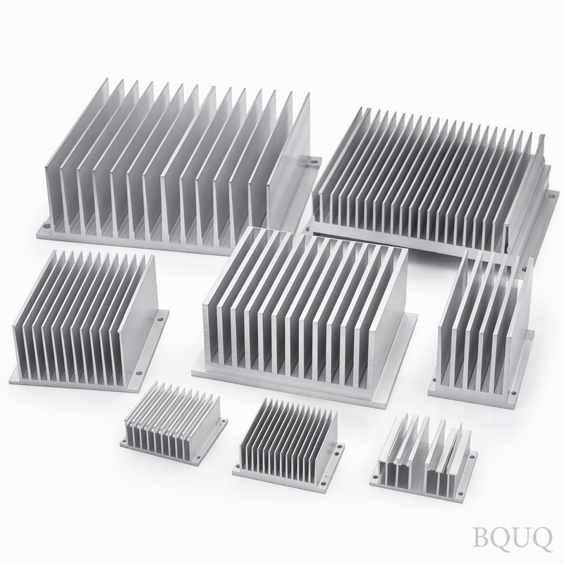
The direct answer is that heat sink designs for 800W+ GPUs are evolving from passive extruded aluminum fin stacks to hybrid vapor chamber and liquid-cooled cold plate assemblies with copper fin densities exceeding 30 fins per inch (FPI) and base plate flatness tolerances of 0.02 mm. For thermal loads above 800W, the limiting factor is no longer the heat sink surface area but the thermal interface resistance and the spreading resistance within the base plate, forcing manufacturers to adopt skived fin, vapor chamber, and micro-channel architectures. Additionally, the structural integration of the heat sink with the GPU die via direct liquid cooling (cold plates) is becoming standard for data center accelerators, with a junction-to-ambient thermal resistance target of less than 0.05 °C/W.
What Are the Primary Thermal Failure Points at 800W+ Power Levels?
At 800W, a GPU die (typically 600 mm² to 800 mm²) produces a heat flux of approximately 100 to 133 W/cm², which exceeds the practical limit of conventional heat pipe heat sinks (around 80 W/cm²). The first failure point is the thermal interface material (TIM) between the die and the heat sink base, where a typical thermal paste with 5 W/m·K conductivity can contribute 0.02 °C/W to 0.05 °C/W of resistance, translating to a 16°C to 40°C temperature rise at the die. The second failure point is base plate spreading resistance, where a 3 mm thick copper base (400 W/m·K) spreads heat from a 30x30 mm die to a 120x120 mm fin base, creating a temperature gradient of 15°C to 25°C if not mitigated with heat pipes or vapor chambers.
Why Are Vapor Chambers Replacing Heat Pipes in High-End GPU Heat Sinks?
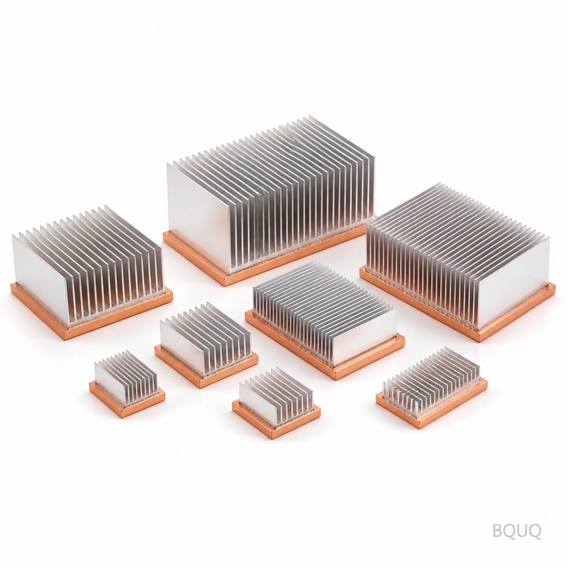
Vapor chambers offer a two-dimensional spreading mechanism with an effective thermal conductivity of 20,000 to 50,000 W/m·K, compared to a solid copper base at 400 W/m·K. For an 800W GPU, a 3 mm thick vapor chamber can reduce base plate spreading resistance from 0.02 °C/W to 0.005 °C/W, lowering the die temperature by 12°C to 15°C under full load. Unlike heat pipes which have a fixed length and limited bending radius, vapor chambers can be fabricated with a custom footprint that matches the PCB layout, allowing direct contact with memory modules and VRM components simultaneously, which is critical for 800W boards where the total board power (TBP) includes 150W to 200W of ancillary component heat.
How Does Fin Density and Skiving Technology Affect 800W+ Cooling Performance?
For air-cooled solutions at 800W, the fin stack must dissipate 800W with a temperature difference of 50°C to 60°C between the fin base and ambient air, requiring a thermal resistance of 0.06 to 0.075 °C/W. Skived fin heat sinks achieve this with fin densities of 25 to 40 FPI, fin heights of 20 to 40 mm, and fin thicknesses of 0.2 to 0.4 mm, whereas traditional extruded fins are limited to 8 to 12 FPI. The skiving process (machining fins from a solid copper block) eliminates the thermal resistance of the fin-to-base joint (solder or epoxy), which typically adds 0.005 to 0.01 °C/W per interface; at 800W, this saves 4°C to 8°C. For comparison, a 120x120x80 mm skived fin heat sink with a 5 mm copper base and 30 FPI can achieve a volumetric thermal resistance of 0.5 °C·cm³/W, which is 40% better than a brazed folded-fin assembly.
Which Material Choices Offer the Best Thermal Performance for 800W+ GPUs?
Copper C1100 (oxygen-free high thermal conductivity, 391 W/m·K) remains the baseline for high-performance heat sinks, but at 800W, the cost of pure copper fin stacks becomes prohibitive (material cost alone for a 1 kg heat sink is $12 to $18 USD). Aluminum 6061-T6 (167 W/m·K) is used for structural frames and mounting plates, but its use as a primary fin material is limited to heat sinks below 400W. For 800W+ applications, the optimal material combination is a copper vapor chamber base (2-3 mm thick) with skived copper fins, or a hybrid design with an aluminum fin stack and embedded copper heat pipes (6 mm diameter, 3-5 pipes) to reduce weight by 30% while maintaining 85% of the thermal performance. For liquid-cooled cold plates, nickel-plated copper (electroless nickel, 5-10 µm thickness) is preferred to prevent galvanic corrosion when using ethylene-glycol coolant, with micro-channel widths of 0.4 to 0.8 mm and channel depths of 1.5 to 3.0 mm.
What Manufacturing Tolerances Are Required for 800W+ Heat Sink Assemblies?
The base plate flatness must be 0.02 mm or better across the entire die contact area to minimize TIM bond line thickness; a 0.05 mm flatness deviation can increase TIM resistance by 50%, resulting in a 10°C rise at 800W. Fin-to-base perpendicularity must be within 0.1 mm over a 40 mm fin height to ensure uniform airflow distribution, and fin spacing tolerance must be ±0.05 mm to maintain consistent pressure drop across the heat sink. For liquid cold plates, the machining tolerance on channel width and depth is ±0.02 mm to ensure uniform coolant flow distribution, and the sealing surface flatness for O-ring or gasket joints must be 0.01 mm to prevent leakage at pressures up to 3 bar. BQUQ maintains these tolerances using 5-axis CNC machining centers with thermal compensation, achieving a repeatability of ±0.005 mm.
How Are Liquid Cooling Cold Plates Redefining Heat Sink Architecture?
For 800W+ GPUs, air cooling requires a heat sink volume of 1.5 to 2.0 liters (e.g., 160x140x80 mm) and a high static pressure fan (20-40 mm H₂O), whereas a liquid cold plate with a 0.5 mm micro-channel array and a 1 L/min coolant flow rate can achieve the same thermal resistance (0.04 °C/W) in a volume of only 0.3 liters. The cold plate base is typically 60x60x10 mm with 50 to 100 parallel micro-channels, and the heat transfer coefficient on the coolant side reaches 20,000 to 40,000 W/m²·K, compared to 100 W/m²·K for air. The pressure drop across a typical GPU cold plate is 0.5 to 1.5 bar at 1-2 L/min, which is within the capability of standard data center CDU (coolant distribution unit) pumps. This shift is driven by the fact that 800W+ GPUs are predominantly installed in rack-mounted servers with existing liquid cooling infrastructure, reducing the total cost of ownership by 30% compared to high-speed fan cooling.
What Are the Cost and Lead Time Trade-offs for Advanced Heat Sink Designs?
| Heat Sink Type | Thermal Resistance (°C/W) | Unit Cost (USD, qty 1000) | Lead Time (weeks) | Max Power (W) |
| Extruded Aluminum (8 FPI) | 0.15 - 0.20 | $8 - $15 | 2 - 3 | 300 |
| Skived Copper (30 FPI) | 0.06 - 0.08 | $25 - $45 | 3 - 4 | 600 |
| Vapor Chamber + Skived Fins | 0.04 - 0.06 | $50 - $80 | 4 - 6 | 800 |
| Liquid Cold Plate (Micro-channel) | 0.02 - 0.04 | $60 - $120 | 4 - 6 | 1200+ |
| Hybrid (Al fins + Cu heat pipes) | 0.08 - 0.10 | $18 - $30 | 2 - 4 | 500 |
The cost escalation from $15 to $120 per unit reflects not only raw material (copper at $9-12/kg vs aluminum at $2.5-3.5/kg) but also the machining time: skiving a fin block takes 15-25 minutes on a CNC machine, while micro-channel cold plates require 30-45 minutes with precision tooling. For production volumes above 5,000 units per year, stamping and brazing processes can reduce cost by 20-30%, but tooling investment is $20,000 to $50,000 for stamping dies, making skiving the most economical choice for medium volumes.
Why Does Thermal Interface Material (TIM) Selection Become Critical Above 800W?
At 800W, a 1°C/W TIM resistance is equivalent to an 800°C temperature rise, so the target TIM resistance must be below 0.01 °C/W. Conventional silicone-based thermal paste (3-5 W/m·K) has a bond line thickness of 50-100 µm under clamping pressure, yielding 0.02-0.04 °C/W, which is unacceptable. High-performance solutions include liquid metal (gallium-indium-tin alloy, 40-80 W/m·K) with a resistance of 0.005-0.01 °C/W, but it requires a nickel-plated surface to prevent gallium corrosion of aluminum. Alternatively, phase-change materials (8-12 W/m·K) with a bond line of 25 µm offer 0.01-0.015 °C/W and are preferred for manufacturability, but they require a clamping pressure of 10-30 psi to achieve optimal wetting. For 800W+ designs, the TIM cost is $3-8 per unit, and the application process (screen printing or stencil) must be controlled to ±10 µm thickness to avoid voids.
FAQ
What Is the Maximum Power a Standard Air-Cooled Heat Sink Can Handle?
A well-designed air-cooled heat sink with a skived copper fin stack and a 120x120x38 mm fan can handle up to 600W to 650W, with a case-to-ambient thermal resistance of 0.06 °C/W. Beyond 800W, the required airflow exceeds 150 CFM and noise levels surpass 60 dBA, making liquid cooling the only practical solution for data center environments.
How Does Die Size Affect the Heat Sink Design for 800W GPUs?
A smaller die (e.g., 25x25 mm) increases heat flux to 128 W/cm², requiring a vapor chamber base to spread heat efficiently, while a larger die (e.g., 35x35 mm) reduces flux to 65 W/cm², allowing a solid copper base with embedded heat pipes. The design rule is that if the die-to-heat-sink base area ratio is less than 1:4, a vapor chamber is mandatory.
When Should I Choose a Vapor Chamber Over a Heat Pipe Assembly?
Choose a vapor chamber when the heat source area is less than 30% of the heat sink base area, or when the heat sink height is limited to less than 25 mm. Vapor chambers are also preferred when multiple heat sources (GPU, memory, VRM) need to be cooled by a single base plate, as they provide uniform temperature distribution across the entire surface.
Which Cooling Method Is Most Cost-Effective for 800W GPU Clusters?
For clusters of 10 or more GPUs, liquid cooling with cold plates is most cost-effective, as it reduces the number of fans and the associated energy consumption (saving $200-400 per GPU per year in electricity). The initial investment in CDUs and manifolds is amortized over 2-3 years, after which the operating cost is 50% lower than air cooling.
How Does Airflow Pressure Drop Affect 800W+ Heat Sink Efficiency?
At 800W, the heat sink must pass 100-150 CFM of air, which requires a pressure drop of 10-30 mm H₂O across the fin stack. Higher fin density (30+ FPI) increases pressure drop exponentially, so the fan must be selected for static pressure rather than airflow, typically using a blower fan with a P-Q curve that matches the heat sink impedance at the operating point.
Can Existing Heat Sink Designs Be Retrofitted for 800W GPUs?
Retrofitting an existing heat sink designed for 350W to handle 800W is not recommended, as the base plate thickness and fin area are undersized by at least 50%. However, adding a secondary liquid cold plate in series with the existing air-cooled heat sink can reduce the thermal resistance by 30-40%, extending the life of the original design, but the total cost is often higher than a purpose-built solution.
What Testing Standards Are Used to Validate 800W+ Heat Sinks?
The standard test method is based on JEDEC JESD51-12, which specifies a thermal test die (e.g., 30x30 mm) mounted on the heat sink with a controlled TIM, and the case-to-ambient thermal resistance is measured in a wind tunnel at a defined airflow rate. For liquid cooling, the cold plate is tested with a calibrated fluid loop at 25°C inlet temperature and 1 L/min flow rate, measuring the junction-to-coolant thermal resistance with an accuracy of ±3%.
The evolution of heat sink design for 800W+ GPUs is fundamentally a transition from passive air-cooled structures to active liquid-cooled and vapor-chamber-based systems, driven by the physics of heat flux and spreading resistance. For engineers specifying these components, the key parameters are base plate flatness (0.02 mm), fin density (30+ FPI for air, 0.5 mm channels for liquid), and TIM resistance (below 0.01 °C/W), with unit costs ranging from $50 to $120 for high-performance solutions. BQUQ, with 20 years of CNC machining and metal stamping experience in Dongguan, manufactures precision heat sinks and cold plates with tolerances down to ±0.005 mm, and offers a 12-hour quoting service for custom designs. Contact our engineering team at sc@bquq.com or WhatsApp +86 13713157787 for a thermal simulation and cost estimate, or visit www.bquq.com to download our heat sink design guide.
Related Articles
- Patent Wars: Intellectual Property Pattern and Risks of Global Hardware Heat Sink Technology
- Smaller Is Harder: The Technical Limits and Innovations of Ultra-Thin Heat Sinks in Consumer Electronics
- From Macro Base Station to Edge Box: Transforming Heat Sink Requirements in Communication Network Evolution


