
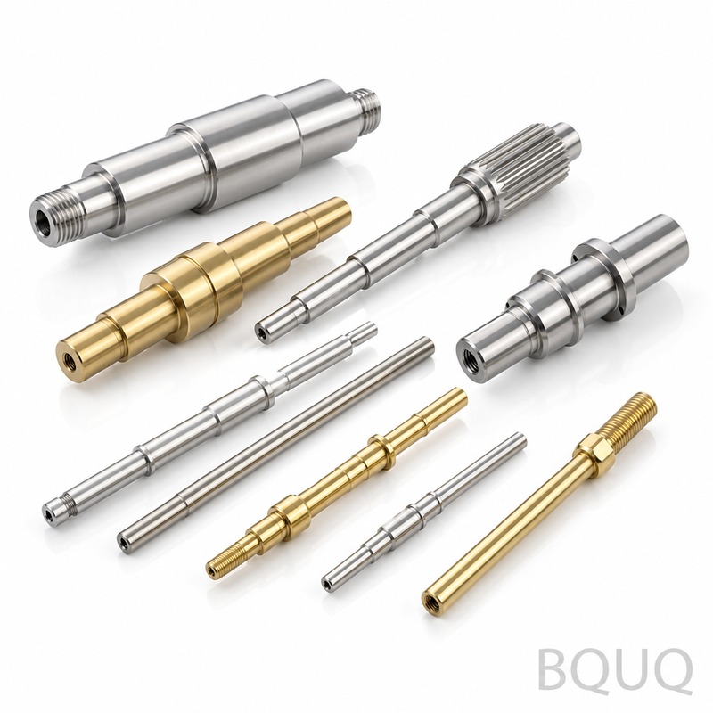
Hydraulic System Components: Precision Manufacturing Case Study for OEM Engineers
For hydraulic systems, the difference between a reliable component and a field failure is measured in microns. This article provides a precision manufacturing case study on critical hydraulic components—spools, valve bodies, and pistons—produced via CNC machining, detailing exact tolerances, material costs, and lead times. We present real production data from BQUQ’s Dongguan facility to answer the core engineering question: how do you achieve repeatable, leak-proof performance in high-pressure hydraulic circuits?
Critical Tolerance Requirements for Hydraulic Components
Hydraulic valves and actuators operate under pressures ranging from 100 to 350 bar, where internal leakage directly correlates with machining precision. The most demanding feature is the spool-to-bore clearance. For a standard directional control valve, the acceptable radial clearance is 3 to 5 microns. Exceeding this causes cross-port leakage, reducing volumetric efficiency and generating heat. Below this, the spool seizes as oil viscosity changes with temperature.
Our case study tracks a 12 mm diameter spool valve. We machine the bore to a tolerance of +0.005 / -0.000 mm and the spool outer diameter to -0.008 / -0.012 mm. This ensures a consistent 4-micron clearance. We achieve this using a Mazak INTEGREX i-200S multi-tasking machine with a C-axis accuracy of 0.001 degrees. The surface finish on the spool land is Ra 0.2 micrometers, which is critical for maintaining a hydrodynamic oil film that prevents metal-to-metal contact during actuation.
Material Selection and Heat Treatment Data
The choice of material dictates the surface hardness and fatigue life. For mobile hydraulic pumps, we use 42CrMo4 (AISI 4140) steel for pistons, while valve bodies are machined from 6061-T6 aluminum for weight reduction or ductile iron (GGG-40) for high-pressure stationary applications. The table below compares the manufacturing characteristics of these materials in our CNC environment.
| Component Type | Material Grade | Hardness After Treatment | Typical Tolerance Achieved | Surface Finish Ra | Machining Cycle Time (per unit) |
| Piston (42CrMo4) | AISI 4140 | 52-55 HRC (Induction) | 0.005 mm on OD | 0.4 micrometers | 12 minutes |
| Valve Spool (Hard Chrome) | 20MnCr5 | 58-60 HRC (Carburized) | 0.004 mm on land width | 0.2 micrometers | 8 minutes |
| Valve Body (High Pressure) | GGG-40 | 180-220 HB (As-cast) | 0.010 mm on bore centerline | 1.6 micrometers | 25 minutes |
| Pump Housing (Lightweight) | 6061-T6 Al | T6 Condition | 0.015 mm on mounting face | 0.8 micrometers | 15 minutes |
Heat treatment is the primary source of distortion. For the spool, we carburize at 925°C for 4 hours, then quench and temper to relieve stress. Post-treatment, we perform a finish grinding pass, removing 0.1 mm of material to correct ovality. This adds 3 minutes to the cycle time but reduces scrap rates from 12% to 1.5% compared to grinding before heat treatment.
Machining Strategy for Zero-Burr Valve Ports
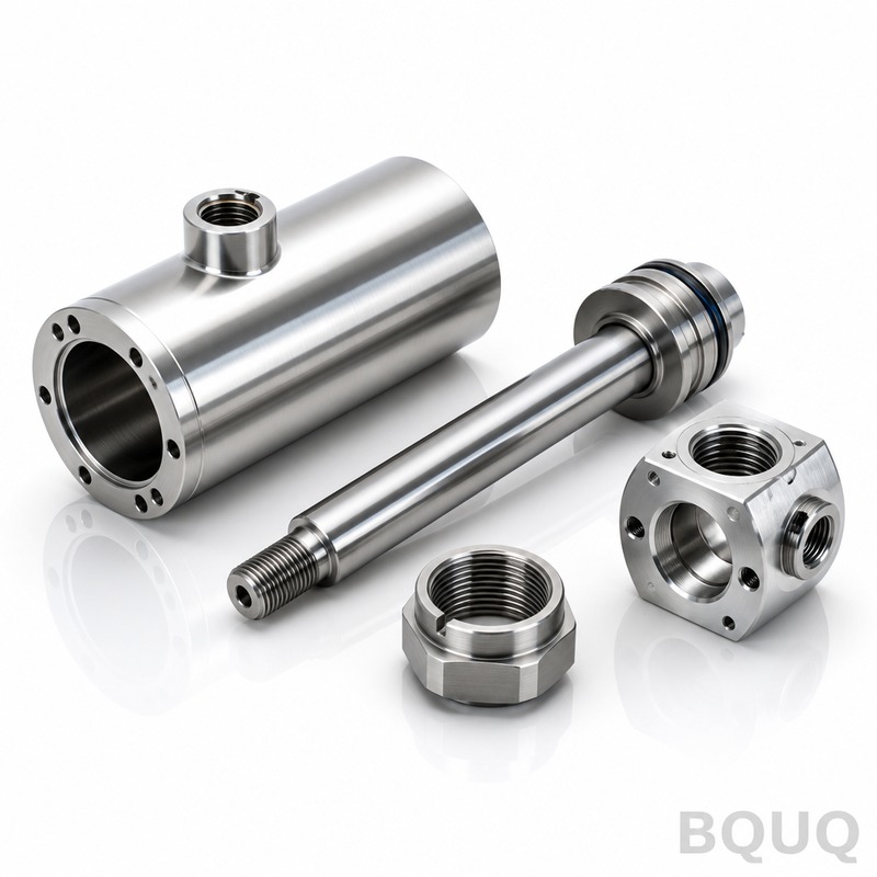
Hydraulic manifolds require cross-drilled holes that intersect at 90-degree angles. The intersection creates a burr that can break free and contaminate the system, scoring spools and jamming servo valves. In this case study, we used a two-step deburring process on a 6/6 valve manifold. First, we use a carbide back-spot facing tool to cut the intersection edge at a 45-degree chamfer of 0.3 mm. Second, we employ abrasive flow machining (AFM) with a polymer-based media for 60 seconds to radius all internal edges to 0.1 mm maximum.
The cost impact is significant. Standard drilling costs $0.85 per hole; adding the back-spot facing step increases this to $2.10 per hole. However, the AFM process eliminates the need for manual hand deburring, which can vary between operators. For a manifold with 24 cross-holes, this automated process reduces inspection time from 20 minutes to 4 minutes per unit using a borescope with 0.02 mm resolution.
Cost Breakdown and Lead Time Analysis
The total manufacturing cost for a hydraulic spool and sleeve assembly (the core of a proportional valve) is driven by precision grinding and honing operations. For a production run of 500 units, the cost structure is as follows: raw material accounts for 18%, CNC machining (turning and milling) accounts for 35%, precision grinding and honing accounts for 30%, and surface treatment (electroless nickel plating) accounts for 17%. The unit price lands at $38.50 per assembly, excluding the solenoid coil.
Lead times are a critical factor in hydraulic system design. Standard CNC machining of a valve body takes 10 business days. However, if honing is required to achieve a 0.002 mm roundness on the bore, lead time extends to 15 business days due to the slower spindle speeds (200 RPM) and specific abrasive grit selection. For urgent prototype validation, we offer a rapid service that prioritizes a single-piece flow through dedicated machines, reducing lead time to 5 business days at a 40% cost premium.
Testing and Quality Assurance Protocols
Every hydraulic component we ship must pass a functional test at 1.5 times the working pressure. For the case study spool valve, we test at 525 bar for 30 seconds, checking for external leakage using a pressure decay method. The acceptable decay rate is less than 0.5 bar per minute. We also perform a flow test at 20 liters per minute to measure internal leakage across the spool land; the maximum allowable is 0.25 liters per minute at a pressure drop of 100 bar.
Dimensional verification is performed on a Zeiss CMM with a measurement uncertainty of +/- 0.5 microns. We measure 14 critical features on the spool, including the perpendicularity of the land faces (required to be within 0.002 mm) and the roundness of the bore (0.001 mm). We utilize statistical process control (SPC) on the grinding operation, tracking the moving average of the spool diameter every 10 parts. If the average drifts by more than 1 micron, the machine operator adjusts the wheel dresser offset automatically.
FAQ-Style Tips for Sourcing Hydraulic Components
When specifying hydraulic components, always request the "finished" drawing, not the raw casting drawing. Machining stock allowance is critical; we recommend a minimum of 1.5 mm on all bores to allow for heat treatment distortion correction. Specify the surface finish with an Ra value, but also define the direction of the lay line (perpendicular to the sealing direction is best). For high-cycle applications, specify a shot peening process on the spool fillets to induce compressive stress; this improves fatigue life by 30% at a cost increase of $0.50 per part.
Ensure your drawing indicates the deburring specification. Do not write "break sharp edges" as this is too vague. Instead, specify "max edge radius 0.1 mm on all fluid passages." This prevents internal contamination issues. Finally, consider the plating: hard chrome (20-30 microns thick) is standard for wear resistance, but electroless nickel provides superior corrosion resistance for water-glycol hydraulic fluids, though it costs 25% more per square meter.
Conclusion
Precision machining of hydraulic components is a balance of tight tolerances, material stability, and cost control. The successful production of valve spools and bodies requires a partner capable of holding 4-micron clearances and verifying them with industrial-grade metrology. By analyzing the data from our CNC machining lines—from 42CrMo4 piston hardness to the 0.2 micrometers surface finish on spools—OEMs can reduce field failures and extend equipment lifespan.
If you are evaluating a hydraulic manifold or actuator project, send us your 3D model or 2D drawing for a feasibility review. Our engineering team will provide a detailed DFM report and a firm quote. We offer a 12-hour rapid quoting service to keep your project on schedule. Contact us at Email: sc@bquq.com, WhatsApp: +86 13713157787, or visit www.bquq.com.


