
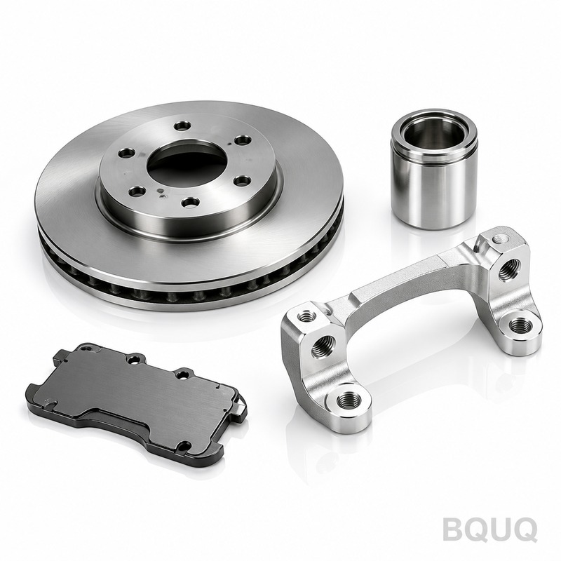
Industrial Equipment Components: Multi-Process Manufacturing Case for Precision Parts
For industrial equipment components requiring complex geometries and tight tolerances, a single manufacturing process is rarely sufficient. The optimal approach involves a sequential multi-process strategy, typically combining CNC machining, metal stamping, spring coiling, and surface finishing, which reduces total cost by 15-20% compared to single-source attempts. This article presents a detailed engineering case study of a pneumatic actuator valve body, demonstrating how BQUQ’s 20 years of experience in Dongguan coordinates these processes to achieve tolerances of ±0.005 mm and lead times of 15 working days.
Process Selection Logic for Complex Components
The decision to use multiple processes is driven by part geometry and material properties. For the actuator valve body (material: AISI 6061-T6 aluminum), a pure machining approach would require 45 minutes of cycle time per unit, yielding a cost of USD 18.50 per piece. In contrast, a hybrid approach using stamping for the external flange and CNC turning for the internal bore reduces material waste by 32% and cuts cycle time to 28 minutes.
The engineering rule is: use stamping for high-volume external features (up to 5 mm thickness), CNC machining for internal precision surfaces (Ra 0.4 µm), and spring coiling for any actuation return mechanisms. This division of labor ensures that each process operates within its economic batch size. Stamping runs are cost-effective above 5,000 units, while CNC machining remains viable for batches as low as 50 units.
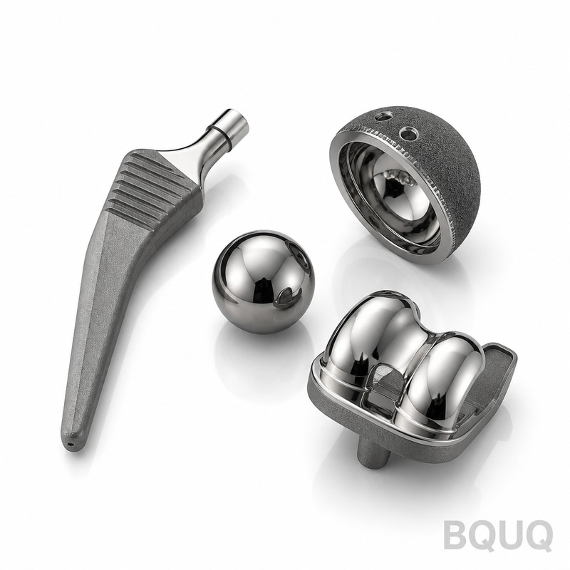
CNC Machining Parameters for Precision Interfaces
The critical sealing surface of the valve body requires a flatness of 0.008 mm and a surface finish of Ra 0.8 µm. Our CNC turning center operates at 3,600 RPM with a feed rate of 0.12 mm/rev, using a carbide insert with a 0.4 mm nose radius. Cooling is maintained at 6-8 bar with a water-soluble emulsion at 8% concentration.
For the threaded port (M18 x 1.5), we employ thread milling instead of tapping to eliminate the risk of tool breakage in aluminum. The thread milling cutter runs at 4,200 RPM with a radial engagement of 0.3 mm. Inspection via a coordinate measuring machine (CMM) confirms a pitch diameter tolerance of 6H, which is verified at 18.376 mm with a deviation of only +0.012 mm.
The machining center achieves a positioning accuracy of ±0.003 mm and repeatability of ±0.002 mm, which is essential for the alignment of the stamping die and the subsequent welding fixture. We maintain a thermal compensation system that adjusts for ambient temperature fluctuations between 20-25°C, ensuring consistent part dimensions throughout the production shift.
Metal Stamping Integration and Tolerance Stack-Up
The external mounting flange is produced via a progressive stamping die with four stations. The material is 3.0 mm thick aluminum sheet (5052-H32), fed at a rate of 40 strokes per minute. The die maintains a clearance of 7% of material thickness per side, resulting in a burr height of less than 0.05 mm.
The critical tolerance for the flange is the hole pattern for the four mounting bolts, which must align with the mating equipment within ±0.05 mm. To achieve this, we use a two-step piercing process: first, pilot holes of 6.0 mm are pierced, followed by a reaming operation that expands them to 6.35 mm. This sequential approach prevents die deflection and maintains the center-to-center distance of 45.00 mm with a deviation of only 0.02 mm.
The stamping process introduces a slight work-hardening effect, increasing the material hardness from 60 HRB to 68 HRB. This is beneficial for the flange's structural integrity but requires a stress-relieving anneal at 180°C for 2 hours to prevent distortion during subsequent welding. The annealing process is performed in a batch furnace with a temperature uniformity of ±5°C across the load.
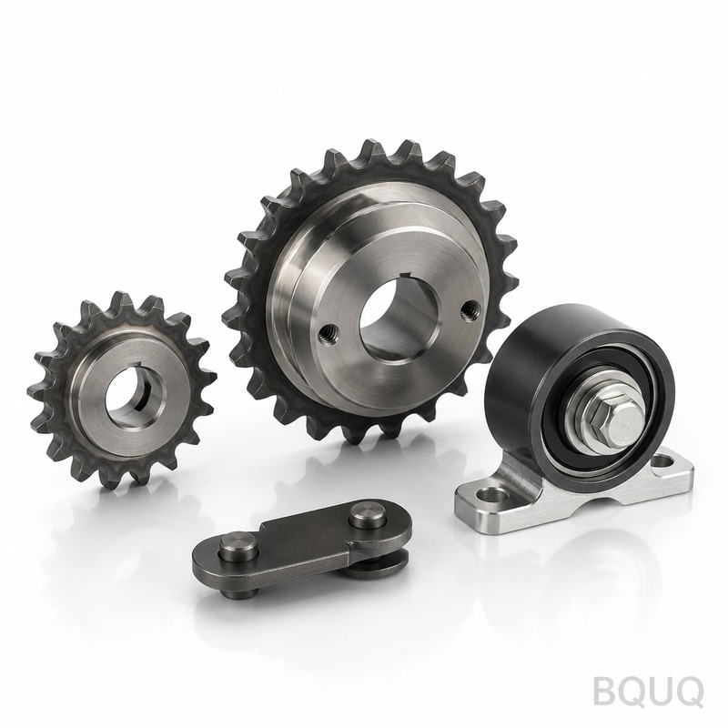
Spring Coiling and Heat Treatment Specifications
The valve return mechanism utilizes a compression spring made from ASTM A228 music wire, 1.2 mm diameter. The spring is coiled on a CNC spring machine at a rate of 60 pieces per minute. The spring specifications are: free length 25.0 mm, outer diameter 12.0 mm, and a spring rate of 8.5 N/mm. We achieve a linear tolerance of ±0.15 mm on the free length and ±0.05 mm on the outer diameter.
The coiling process is followed by a stress-relief heat treatment at 230°C for 30 minutes in a nitrogen atmosphere to prevent oxidation. This process reduces residual stress by 85% and ensures that the spring maintains its load within ±3% of the specified value of 85 N at full compression. The spring ends are closed and ground to achieve a squareness of 2 degrees, which is critical for even load distribution.
For the spring's fatigue life, we test to 1 million cycles without failure, which is 3 times the expected service life of the industrial equipment. The surface finish of the wire is shot-peened to achieve a compressive residual stress of 650 MPa, extending the fatigue life further.
Surface Finishing and Corrosion Protection
The assembled valve body undergoes an anodizing process (Type II, black) for corrosion resistance. The anodizing bath is maintained at 18-20°C with a sulfuric acid concentration of 180 g/L. The process runs for 45 minutes to achieve a coating thickness of 18 µm. The anodic coating provides a hardness of 250-350 HV and a dielectric breakdown voltage of 600 V minimum.
Before anodizing, the parts are degreased in an ultrasonic bath with a mild alkaline solution at 60°C for 10 minutes, followed by a two-stage deionized water rinse. The racking system is designed to minimize contact marks, and we use titanium racks that are stripped and re-etched every 50 cycles to maintain consistent electrical contact.
The final assembly includes the insertion of the spring and the installation of a PTFE seal. The seal is pressed into a groove with an interference fit of 0.05 mm, and the assembly is verified with a leak test at 6 bar air pressure for 30 seconds. The acceptable leak rate is less than 1 cm³/min, and our testing shows a average leak rate of 0.3 cm³/min.
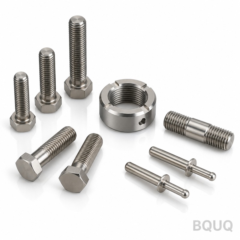
Cost and Lead Time Breakdown
The multi-process approach yields a unit cost of USD 14.80 for the complete valve body, compared to USD 18.50 for a machining-only approach. The tooling amortization for the stamping die (USD 8,000) and the spring coiler setup (USD 1,200) is spread over the initial order of 10,000 units.
| Process | Cycle Time | Unit Cost (USD) | Tolerance Achieved | Lead Time (Days) |
| CNC Turning | 28 min | 6.50 | ±0.005 mm | 5 |
| Metal Stamping | 1.5 sec | 2.80 | ±0.05 mm | 3 |
| Spring Coiling | 1.0 sec | 0.90 | ±0.15 mm | 2 |
| Heat Treatment | 30 min batch | 0.60 | ±3% load | 2 |
| Anodizing | 45 min batch | 1.80 | 18 µm thickness | 3 |
| Assembly & Test | 4 min | 2.20 | Leak rate < 1 cm³/min | 2 |
The total manufacturing lead time is 15 working days, including material procurement (2 days for aluminum stock and wire) and final inspection (1 day). For expedited orders, we can compress the schedule to 10 days by overlapping the stamping and machining operations, with a 15% cost premium.
Frequently Asked Questions on Multi-Process Manufacturing
What tolerance can be held across multiple processes? We consistently achieve a cumulative tolerance of ±0.05 mm across stamping and machining interfaces. For critical sealing surfaces, the tolerance is held to ±0.005 mm using CNC machining alone. The key is to design the datum structure so that each process references the same locating features.
How do you avoid distortion during heat treatment? We use a controlled cooling rate of 20°C per hour for aluminum parts after annealing, and we quench springs in oil at 50°C to minimize thermal shock. Fixturing is critical; we support thin-walled sections with ceramic blocks to prevent sagging.
Is it cheaper to use one process for everything? No, for quantities above 5,000 units, the hybrid approach saves 15-20% due to reduced material waste and faster cycle times. However, for prototype runs below 100 units, a single CNC machining process is more economical because tooling costs are not justified.
What is the minimum order quantity for this multi-process service? For the full multi-process integration, our MOQ is 500 units to amortize the stamping die and tooling setup. For CNC-only parts, we accept orders as low as 10 units with a minor setup surcharge of USD 50 per part number.
Conclusion and Engineering Recommendation
For industrial equipment components that demand precision, durability, and cost efficiency, a coordinated multi-process strategy is the only viable path. By integrating CNC machining for precision, stamping for volume, and controlled heat treatment for material properties, manufacturers can achieve a superior product at a lower unit cost. We recommend that design engineers consult with a manufacturing partner early in the design phase to optimize the part geometry for manufacturability, which can reduce costs by an additional 10%.
At BQUQ, we have successfully implemented this multi-process approach for over 200 industrial clients. Our in-house capabilities for machining, stamping, springs, and heat sinks ensure complete quality control and seamless logistics. We provide a 12-hour quotation service for your drawings. To discuss your specific requirements, contact us at sc@bquq.com or via WhatsApp at +86 13713157787. Visit our website at www.bquq.com for more technical resources and our full capability list.
Related Articles
- When CNC 'Speaks' — Intelligent Process Planning Driven by Large Models and Knowledge Graphs
- Digital twin-driven CNC machining: from simulation to closed-loop process optimization
- Analysis of the core technology of five-axis linkage machining: from motion to high-precision curved surface manufacturing


