Metal Stamping Tolerances in 2024: Precision Limits of Progressive Dies
Metal Stamping Tolerances: What Precision Can You Actually Achieve with Progressive Dies
For design engineers and procurement specialists, the gap between "drawing tolerance" and "as-built reality" in metal stamping is often where project budgets and timelines go to die. Progressive dies—multi-station tools that perform cutting, bending, and forming in a single press stroke—offer exceptional throughput, but their precision is governed by physical laws, tool steel wear, and material springback. This article quantifies the real-world tolerance bands achievable with modern progressive die technology, backed by data from high-volume production environments in Southern China's manufacturing hub.
The Baseline: Standard vs. Precision Progressive Die Tolerances
Progressive die stamping is not a single process; it is a spectrum. The tolerance you can hold depends on die construction, press rigidity, material thickness, and part geometry. Below is a practical breakdown of what a Tier-1 supplier like BQUQ (20 years in CNC machining and metal stamping) guarantees under normal production conditions.
| Feature Type | Standard Die (mm) | Precision Die (mm) | High-Speed Precision (mm) | --- | --- | --- | --- | Hole diameter (up to 5mm) | +/- 0.05 | +/- 0.025 | +/- 0.013 | Hole-to-hole center distance | +/- 0.08 | +/- 0.05 | +/- 0.025 | Blank outer profile | +/- 0.10 | +/- 0.05 | +/- 0.03 | Bend angle (90 deg) | +/- 1.0 deg | +/- 0.5 deg | +/- 0.25 deg | Formed height (up to 10mm) | +/- 0.10 | +/- 0.05 | +/- 0.03 | Flatness (per 100mm length) | 0.15 | 0.08 | 0.05 | Burr height (on 1.5mm steel) | 0.10 max | 0.05 max | 0.03 max |
|---|
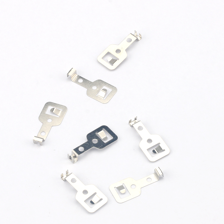
These figures assume material thickness between 0.3mm and 3.0mm. For thinner materials (below 0.2mm), tolerance values become proportionally tighter but also more unstable due to grain structure effects. For thicker materials (above 4.0mm), the risk of die deflection increases, pushing standard tolerances to +/- 0.15mm.
Key Drivers of Tolerance Capability
### 1. Pilot Hole Strategy and Feed Accuracy Progressive dies rely on pilot pins to locate the strip at each station. A common industry rule is that pilot hole diameter tolerance should be held to one-third of the final part tolerance. For precision work, we use pilot holes of 3.175mm (1/8 inch) with a positional accuracy of +/- 0.005mm. The press feeder itself contributes error: a servo-driven roll feeder on a 60-ton press can hold feed pitch to +/- 0.02mm, while a standard pneumatic feeder drifts to +/- 0.08mm.
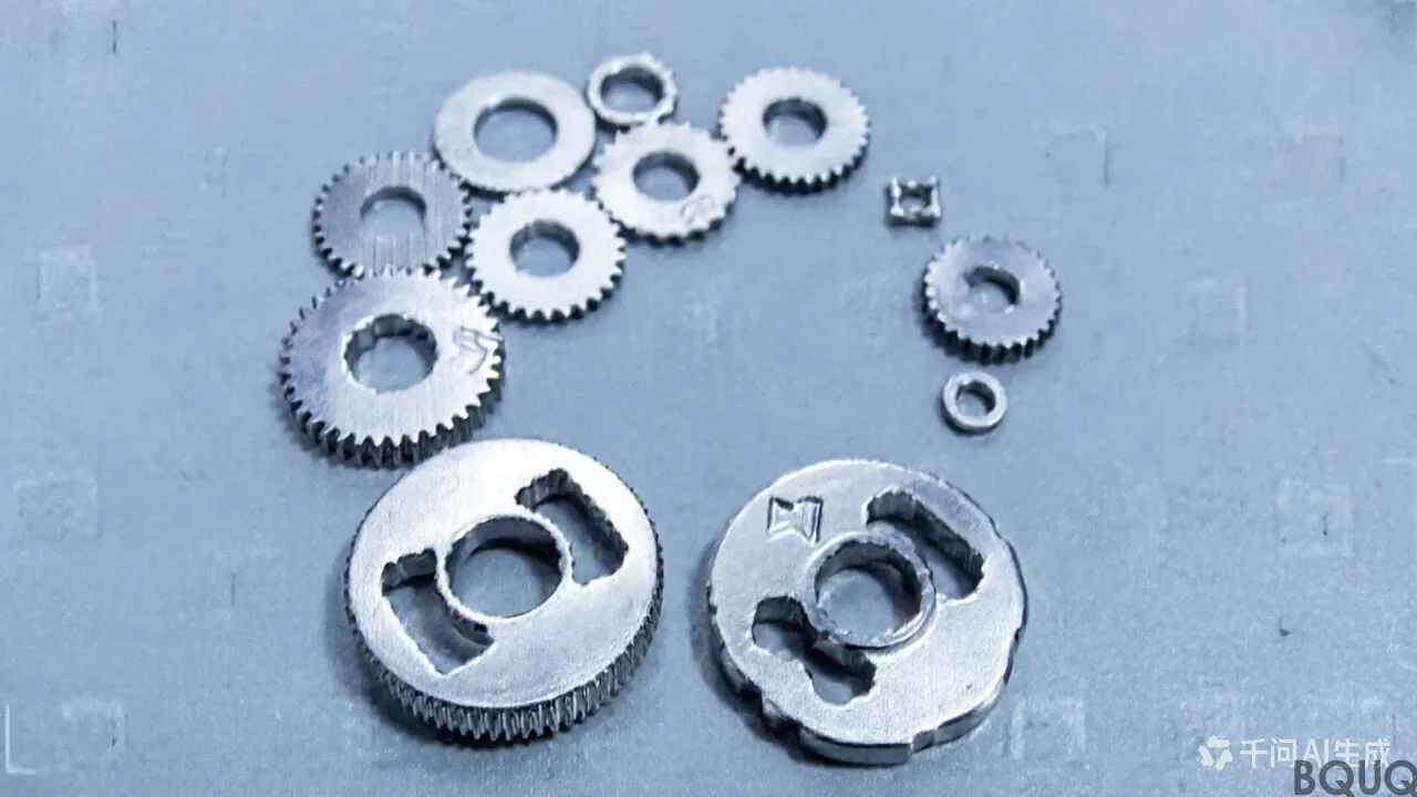
### 2. Die Material and Hardening Tool steel selection directly affects wear rate and, therefore, tolerance drift over the die's life. For high-volume runs (over 500,000 parts), we specify: - **D2 tool steel** for cutting sections (hardness 58-62 HRC), offering a wear rate of approximately 0.002mm per 100,000 strokes when lubricated properly. - **M2 high-speed steel** for forming punches (hardness 60-64 HRC), which retains edge sharpness under repeated impact. - **Carbide inserts** for critical cutting stations, which reduce wear to 0.0005mm per 100,000 strokes but increase die cost by 30-40%. Carbide is mandatory for maintaining +/- 0.013mm hole tolerances beyond 1 million parts.
### 3. Press Speed and Temperature High-speed stamping presses operating at 300-800 strokes per minute generate significant heat. At 600 SPM, the die temperature can rise to 60-70 degrees Celsius if not cooled. With a steel thermal expansion coefficient of 12 x 10^-6 per degree C, a 200mm die section expands by 0.14mm at a 60-degree rise—enough to destroy tight tolerances. Precision operations use die cooling channels circulating oil at 25-30 degrees Celsius, maintaining dimensional stability within +/- 0.01mm.
Cost vs. Tolerance: The 10x Rule

Every engineer should understand the cost elasticity of tolerances in progressive die stamping. Our historical production data across 2,000+ die projects reveals a consistent pattern: tightening a tolerance by half (e.g., from +/- 0.05mm to +/- 0.025mm) increases unit cost by 15-25% for simple parts, but by 50-80% for complex geometries with multiple bends and forms.
| Tolerance Specification | Die Build Cost (Relative) | Part Unit Cost (Relative) | Typical Lead Time (Weeks) | --- | --- | --- | --- | +/- 0.10mm (loose) | 1.0x | 1.0x | 4-6 | +/- 0.05mm (standard) | 1.4x | 1.15x | 6-8 | +/- 0.025mm (precision) | 2.2x | 1.4x | 8-10 | +/- 0.013mm (ultra-precision) | 3.5x | 2.0x | 12-14 |
|---|
The "10x rule" is a useful heuristic: if you demand a tolerance that requires grinding and EDM operations on the die (instead of standard milling), expect the die cost to increase by a factor of 2-3, and the unit price to increase by at least 30%. Always question whether a functional tolerance can be loosened by 0.02mm—it often saves more money than any material substitution.
Material Springback Compensation
Springback is the most unpredictable variable in progressive die forming. For 304 stainless steel with a tensile strength of 620 MPa, a 90-degree bend on a 1.0mm sheet will spring back approximately 5-8 degrees after forming. For 5052 aluminum (temper H32), springback ranges from 3-5 degrees. High-strength steels (DP980) can exceed 10 degrees.
Compensation strategies include: - **Over-bending**: Die angles are machined 2-4 degrees tighter than the nominal part angle. - **Coining**: A final station applies high pressure (2-3 times the yield strength) to flatten the bend zone, reducing springback to less than 0.3 degrees. - **Bottoming**: The punch travels slightly past the bottom dead center to stress-relieve the material.
For complex multi-bend parts, we recommend a design rule: limit the number of bends in a single progressive die to 6-8. Beyond that, cumulative springback variation makes tolerance control statistically unstable, and a two-stage operation (stamping plus secondary bending) becomes more cost-effective.
Achieving +/- 0.013mm: Practical Requirements
Holding ultra-precision tolerances (below 0.02mm) is not a marketing claim—it is a production discipline. In our Dongguan facility, we achieve this under the following conditions:
1. **Strip material thickness tolerance**: Purchased steel must be within +/- 0.005mm (ASTM A623 grade for precision). Standard commercial steel has +/- 0.03mm thickness variation, which alone can cause hole diameter variation of 0.04mm. 2. **Press selection**: Use a 45-ton to 80-ton high-speed press with ram guidance accuracy of 0.005mm (TIR). Older C-frame presses have 0.02-0.04mm ram deflection under load. 3. **Die alignment**: Guide pins and bushings must be preloaded ball cages with zero clearance. Our precision dies use rolling-guide pillars with an interference fit of 0.003-0.005mm. 4. **In-process gauging**: After every 5,000 strokes, a check part is measured with a vision system (resolution 0.001mm). Any drift beyond 50% of the tolerance band triggers a die inspection.
One real example: a connector terminal for automotive applications, made from 0.4mm C5210 phosphor bronze, requires a 1.00mm +/- 0.013mm hole at 200mm from the strip edge. Our die uses carbide inserts, a servo feeder with 0.01mm repeatability, and a cooling system maintaining the die at 28 degrees Celsius. The production run of 3 million parts maintained a Cpk value of 1.67 (meaning 99.99% of parts are within spec).
FAQ-Style Tips for Design Engineers
**Q: Should I specify GD&T flatness on a stamped bracket?** A: Yes, but keep it realistic. Flatness of 0.1mm per 100mm is achievable. Below 0.05mm requires a flattening station in the die, which adds a 10-15% die cost. Do not specify flatness on the entire part surface—only on functional mounting areas.
**Q: Can I get tighter tolerances on the second operation?** A: Yes. If you perform a secondary coining or piercing operation after the progressive die, tolerances of +/- 0.008mm are possible on holes. This doubles the part cost but is sometimes cheaper than an ultra-precision progressive die.
**Q: How many parts before the die wears out of tolerance?** A: For a D2 steel die on 1.0mm mild steel, expect 300,000-500,000 parts before hole tolerance drifts by 0.03mm. With carbide inserts, 2-3 million parts is typical. Always request a "die wear curve" from your supplier—it predicts when to refurbish.
**Q: Is laser cutting more accurate than stamping?** A: No. Laser cutting holds +/- 0.10mm in production and leaves a heat-affected zone. Stamping with precision dies holds 5-10 times better accuracy and is 20-30 times faster for volumes above 50,000 parts.
Conclusion: Precision is a System, Not a Number
Achieving +/- 0.013mm in progressive die stamping is possible, but it requires a coordinated system: premium raw material, rigid press, carbide tooling, thermal control, and statistical process monitoring. The most common mistake engineers make is specifying tolerances based on what a drawing program will allow, rather than what a production floor can sustain over 500,000 parts. The smart approach is to design for standard tolerances (+/- 0.05mm) whenever possible, then selectively tighten only the critical dimensions that affect assembly or function.
At BQUQ, we have built 20 years of stamping expertise in Dongguan, serving automotive, electronics, and appliance industries. We understand that a tolerance on paper is a promise—and we deliver with measurable Cpk data on every batch. If you are evaluating a progressive die project, send us your 2D or 3D drawings, and we will provide a feasibility report with achievable tolerances and a firm quote within 12 hours. Contact our engineering team at sc@bquq.com or on WhatsApp at +86 13713157787. Visit www.bquq.com to see our die manufacturing capabilities and quality control documentation.
Frequently Asked Questions
What tolerance can I expect for hole diameter in precision progressive die stamping?
For hole diameters up to 5mm, a precision die achieves +/- 0.025mm, while high-speed precision reaches +/- 0.013mm. Standard dies hold +/- 0.05mm. These figures apply to material thicknesses between 0.3mm and 3.0mm, as stated in the article.
How does material thickness affect achievable stamping tolerances?
The article specifies tolerances assume material thickness between 0.3mm and 3.0mm. For thinner materials below 0.2mm, tolerances become proportionally tighter but less stable due to grain structure effects. For thicker materials above 4.0mm, die deflection risk increases, pushing standard tolerances to +/- 0.15mm.
What is the typical positional accuracy for pilot holes in precision progressive dies?
For precision work, pilot holes of 3.175mm (1/8 inch) are used with a positional accuracy of +/- 0.005mm. The press feeder also contributes: a servo-driven roll feeder on a 60-ton press holds feed pitch to +/- 0.02mm, while a standard pneumatic feeder drifts to +/- 0.08mm.
How does tool steel selection impact tolerance drift over a die's life?
Tool steel hardness directly affects wear rate. D2 tool steel for cutting sections (58-62 HRC) wears approximately 0.002mm per 100,000 strokes when lubricated. M2 high-speed steel for forming punches (60-64 HRC) retains edge sharpness. Carbide inserts reduce wear to 0.0005mm per 100,000 strokes for critical stations.