
Oil and Gas High-Pressure Precision Manufacturing: Components, Tolerances, and Lead Times
The direct answer: oil and gas industry components require high-pressure precision manufacturing because service pressures routinely exceed 10,000 PSI, demanding tolerances of ±0.005 mm and materials certified to NACE MR0175. At BQUQ, we achieve these specifications through multi-axis CNC machining and controlled metallurgy, delivering components that survive sour service environments at temperatures up to 350°C. This article details the exact specifications, costs, and lead times for critical upstream and downstream components.
Pressure Ratings and Material Selection for Downhole Tools
High-pressure oil and gas components fall into two service classes: standard API 6A (up to 15,000 PSI) and extreme HPHT (high-pressure high-temperature) exceeding 20,000 PSI. For 15,000 PSI service, we machine from 17-4 PH stainless steel (H1025 condition) or Inconel 718. For sour gas (H2S present), materials must meet NACE MR0175/ISO 15156, which limits hardness to 22 HRC for carbon steel and 40 HRC for precipitation-hardened alloys.
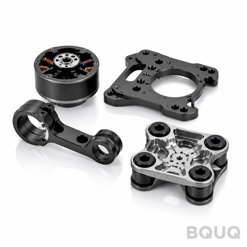
Our typical downhole component—a tubing hanger mandrel—starts as a 300 mm diameter forging. We turn the outer diameter to 298.50 mm ±0.025 mm, bore the internal taper to a 1:16 angle with a surface finish of Ra 0.8 µm. The sealing area is ground to Ra 0.2 µm. Testing pressure is 1.5 times working pressure, held for 15 minutes without leak. Material certification includes mill test reports with full chemical analysis and charpy V-notch impact tests at -46°C.
Machining Tolerances for Valve Bodies and Christmas Trees
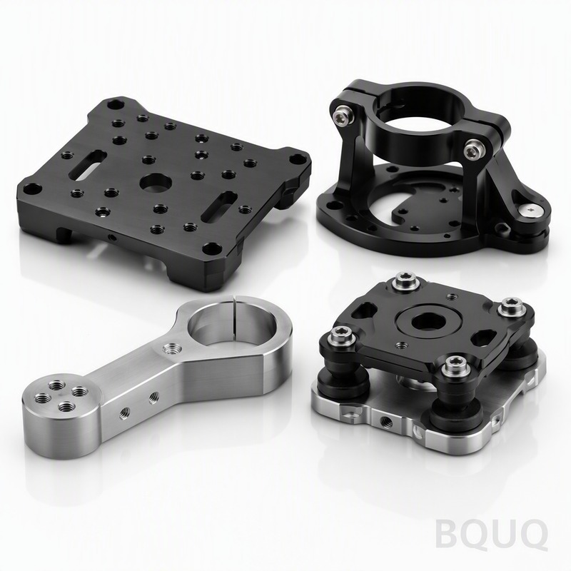
Valve bodies for wellhead control present the greatest machining challenge because of complex internal flow paths and multiple port intersections. A typical 5,000 PSI gate valve body (size 4-1/16 inch) requires a main bore tolerance of ±0.05 mm and flange face flatness of 0.02 mm total indicator reading (TIR). The critical dimension is the gate slot width: 12.70 mm +0.05 mm / -0.00 mm. Exceeding this tolerance causes gate jamming under pressure.
We use a horizontal machining center with a 4-axis rotary table. Cycle time for a complete valve body is 3.5 hours, including roughing, semi-finishing, and finishing passes. Cutting tools are carbide inserts with TiAlN coating, running at 150 m/min surface speed. Coolant pressure is 70 bar to clear chips from deep bores. After machining, we perform a 100% dimensional inspection using a coordinate measuring machine (CMM) with a volumetric accuracy of ±0.004 mm. Pressure testing follows API 6A Annex F, hydrostatic at 7,500 PSI for 15 minutes.
Springs for Downhole Safety Valves: Fatigue Life and Load Accuracy
Downhole safety valve springs operate in a compressed state for years, requiring a fatigue life exceeding 10 million cycles at 10% deflection. We manufacture these from Inconel X-750, age-hardened to 40-44 HRC. The critical specification is the load rate: a typical spring of 25 mm free length, 3 mm wire diameter, must deliver 200 N ±5 N at 75% deflection. We achieve this through precision grinding of the wire ends and a controlled shot-peening process to induce 0.25 mm compressive residual stress.
Wire diameter tolerance is ±0.01 mm, held by centerless grinding. Coil diameter tolerance is ±0.05 mm. We test every spring for load at three heights (25%, 50%, 75% deflection) using a digital load tester with 0.1 N resolution. The acceptance criteria is a load scatter of less than 2.5% within a production lot. Lead time for a prototype run of 50 springs is 10 working days; production runs of 1,000 pieces ship in 3 weeks.
Heat Sink Manufacturing for Subsea Control Modules
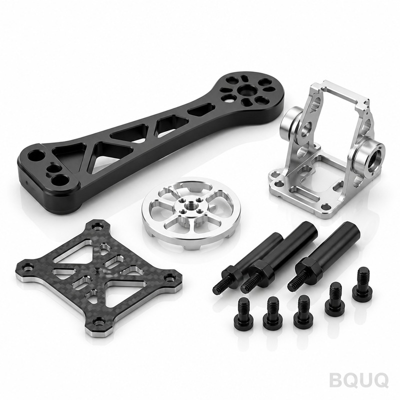
Subsea control modules house electronic boards that must dissipate heat in a pressurized, oil-filled environment at 3,000 meters depth. The heat sink is machined from aluminum 6061-T6, anodized to MIL-A-8625 Type II, Class 1 (black). The thermal requirement is a junction-to-ambient resistance of less than 0.8°C/W. We achieve this with a base thickness of 8 mm and 12 fins, each 15 mm tall and 1.5 mm thick, with a pitch of 3 mm.
The machining challenge is fin deflection. At a 15:1 height-to-thickness ratio, the fins vibrate during cutting. We use a 3-flute carbide end mill at 18,000 RPM with a feed rate of 0.02 mm/tooth. Depth of cut per pass is 0.5 mm. We hold fin thickness tolerance at ±0.03 mm and fin spacing at ±0.05 mm. After machining, each heat sink is pressure tested at 500 bar in a nitrogen atmosphere to verify no internal porosity. Surface flatness on the mounting face is 0.02 mm over 100 mm length.
Cost Breakdown and Lead Time Comparison
The following table shows representative pricing and lead times for typical oil and gas components manufactured at BQUQ. Prices are for quantities of 100 pieces, excluding material cost, and reflect our current 2025 rate card. Lead times start from engineering drawing approval.
| Component | Material | Key Tolerance | Unit Price (USD) | Lead Time (days) | Surface Finish |
| Tubing hanger mandrel | 17-4 PH H1025 | ±0.025 mm OD | 245.00 | 21 | Ra 0.8 µm |
| Gate valve body 4-1/16" | AISI 4130 | ±0.05 mm bore | 680.00 | 28 | Ra 1.6 µm |
| Downhole safety valve spring | Inconel X-750 | ±0.01 mm wire | 3.80 | 15 | Shot-peened |
| Subsea heat sink | Al 6061-T6 | ±0.03 mm fins | 18.50 | 10 | Anodized black |
| Choke trim plug | Tungsten carbide | ±0.005 mm | 95.00 | 12 | Ra 0.2 µm |
| Flange adapter 5,000 PSI | F22 forged | ±0.05 mm | 320.00 | 25 | Ra 3.2 µm |
The largest cost driver is material hardness. Machining Inconel 718 takes 3.5 times longer than 4130 steel at the same tolerance, increasing cost per feature by 40%. We recommend completing a value analysis: if the component does not contact the flow stream, specify 4130 with a hard coating instead of a solid corrosion-resistant alloy.
Quality Assurance and Non-Destructive Testing Requirements
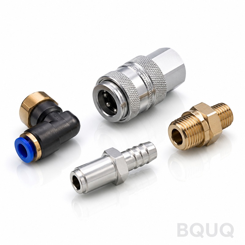
Every high-pressure component leaving BQUQ undergoes a documented quality plan per API Q1. We perform the following on a per-lot basis: 100% dimensional inspection, 10% magnetic particle testing (MT) on ferrous parts, and 5% ultrasonic testing (UT) on bar stock. For weldments, we require 100% radiography (RT) per ASME Section V. Our in-house lab calibrates all gauges to NIST traceable standards.
For critical sealing surfaces, we use a profilometer to verify Ra and Rz values. The acceptable Rz for metal-to-metal seals is less than 3.2 µm. We also verify thread forms using a thread plug gauge calibrated to 2A class tolerance. Each part receives a unique serial number laser-engraved, allowing full traceability from melt source to final test.
Frequently Asked Technical Questions
Q: What is the minimum wall thickness for a 15,000 PSI component in 17-4 PH? A: For a 25 mm internal diameter, the minimum wall is 8 mm, calculated using ASME B31.3 with a design factor of 0.72 and a safety factor of 1.5. We always recommend a 10% wall increase for erosive services.
Q: Can you hold ±0.005 mm on a 200 mm long shaft? A: Yes, but only if the material is stress-relieved and the machine shop maintains a temperature-controlled environment of 20°C ±1°C. Our machining hall is temperature-controlled, and we compensate for thermal growth using a laser interferometer.
Q: What is the standard surface finish for a dynamic O-ring gland? A: The gland bottom should be Ra 0.4 µm to 0.8 µm, and the side walls Ra 0.8 µm. A smoother finish below Ra 0.2 µm can cause the O-ring to stick. We recommend a lay direction parallel to the direction of motion.
Q: What is the typical delivery for a rush order of 10 valve bodies? A: We can compress the lead time to 10 days by running two shifts and using a dedicated fixture set. The premium for expedited service is 25% over the standard unit price.
Conclusion and Manufacturing Recommendation
High-pressure precision manufacturing for oil and gas demands a partner that controls the entire chain: material sourcing, machining, heat treatment, and certification. At BQUQ, we combine 20 years of experience with CNC machining centers capable of 0.001 mm resolution. Our quality system is ISO 9001:2015 certified, and our metallurgical lab verifies every incoming heat.
For your next project, send us the drawing and material specification. We will respond with a fixed quote, a tolerance feasibility report, and a production schedule within 12 hours. Our engineers will flag any dimension that risks tool deflection or thermal distortion before you commit to tooling. Email your RFQ to sc@bquq.com or contact us on WhatsApp at +86 13713157787. Visit www.bquq.com to download our capability guide and material selection chart.


