

Skived Heat Sink Design Guide: Benefits, Limits, and When to Specify
**Introduction**
A skived heat sink is a cooling component manufactured by shaving thin, continuous layers of material—typically copper or aluminum—from a solid block to form tall, dense, and unbroken fins. You should use a skived heat sink when your application demands fin densities above 20 fins per inch (FPI), very low thermal resistance, or anisotropic heat spreading that cannot be achieved with extruded or bonded fin assemblies. For high-power LED modules, laser diodes, and compact IGBT inverters, skiving often outperforms extrusion by 30–50% in thermal efficiency at the same volumetric footprint, though at a 15–25% higher unit cost.

**What Exactly Is a Skived Heat Sink?**
Skiving is a subtractive manufacturing process where a precision cutting tool peels a continuous ribbon of metal from a solid base plate. Unlike extrusion (which pushes heated metal through a die) or forging (which presses metal into shape), skiving does not break the grain structure of the material. This means the fins are integral to the base—there is no solder joint, epoxy bond, or mechanical interface between fin and base. The result is a monolithic structure with zero contact thermal resistance.
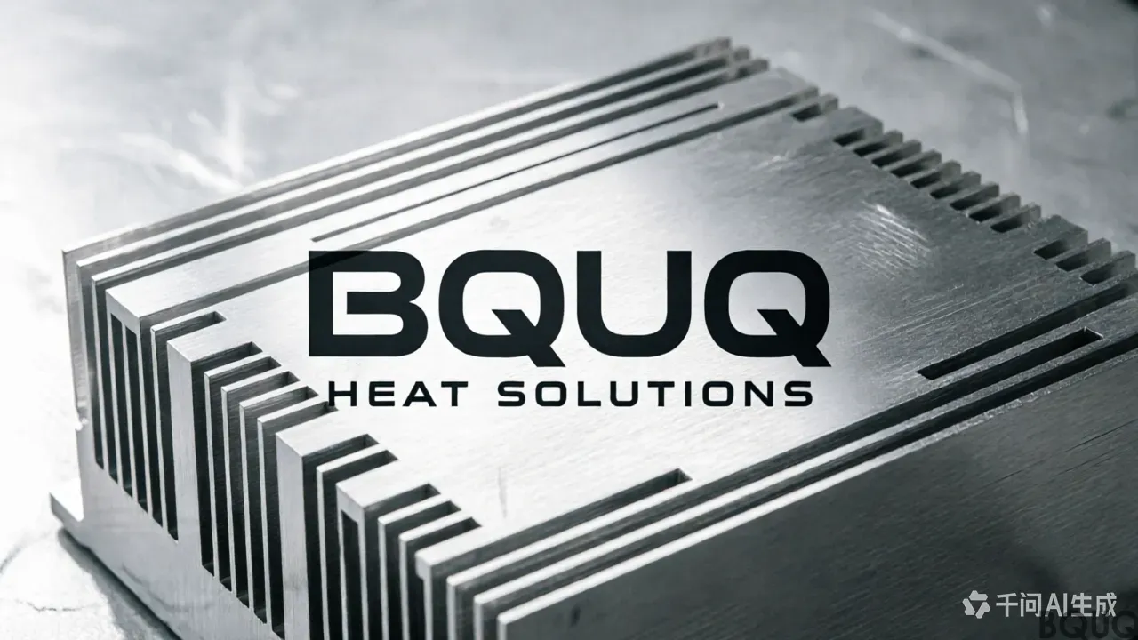
In practice, BQUQ’s skiving line produces fins as thin as 0.3 mm (0.012 in) with fin heights up to 60 mm (2.36 in) and fin pitch ratios of 1:1 to 1:3. A typical skived aluminum heat sink (6063-T5) achieves a fin efficiency of 95–98% at a 3 m/s airflow, compared to 85–90% for an equivalent bonded fin design. The process is also highly repeatable: we hold fin thickness tolerance to ±0.05 mm and base flatness to 0.1 mm over a 300 mm length.
**Skived vs. Extruded vs. Bonded Fin Heat Sinks: A Data-Driven Comparison**

To decide when to use skiving, you must compare it against competing technologies. The table below provides typical specifications from BQUQ’s production lines and industry-standard reference data.
| Parameter | Skived Heat Sink (BQUQ) | Extruded Heat Sink | Bonded Fin (soldered/epoxied) | ----------- | ------------------------ | -------------------- | ------------------------------- | Fin density (FPI) | 20–40 | 4–12 | 8–18 | Minimum fin thickness (mm) | 0.3 | 1.0 | 0.5 | Maximum fin height (mm) | 60 | 100 (limited by die) | 150 (with base) | Fin-to-base joint | None (monolithic) | None (monolithic) | Solder/epoxy (Rth 0.1–0.5 °C/W) | Thermal resistance (aluminum, 100x100x25mm, 2 m/s) | 0.45 °C/W | 0.75 °C/W | 0.55 °C/W | Material options | Al 6063, Al 6061, Cu 110 | Al 6063, Al 6060 | Al + Cu (dissimilar) | Max operating temperature | 250 °C (Al), 400 °C (Cu) | 250 °C (Al) | 150 °C (epoxy limit) | Tooling cost (USD) | $800–$1,500 | $3,000–$8,000 | $500–$1,000 | Unit cost (100 pcs, 100x100x25mm) | $12–$18 | $8–$12 | $10–$15 | Lead time (prototype) | 5–7 days | 10–15 days (die) | 3–5 days | Aspect ratio (height/thickness) | Up to 80:1 | 25:1 | 60:1 |
|---|
**Key takeaway:** Skiving wins when fin density and height are critical. Extrusion wins for low-cost, high-volume, simple geometries. Bonded fins win when you need mixed materials (copper fins on aluminum base) but cannot tolerate the contact resistance of a joint.
**When to Specify a Skived Heat Sink: Five Engineering Scenarios**
1. **High heat flux with limited airflow (natural convection or low CFM fans).** For a 120 mm x 120 mm LED COB array dissipating 150 W, a skived aluminum sink with 25 FPI and 40 mm fin height yields a case-to-ambient thermal resistance of 0.35 °C/W at 1.5 m/s natural convection. An extruded sink at 8 FPI would require 1.8x the base area to achieve the same resistance. Use skiving for any heat flux above 15 W/cm².
2. **Space-constrained electronics (1U servers, compact inverters).** A 1U chassis allows only 44 mm of total height. A skived heat sink with 0.5 mm fins and 0.5 mm gaps provides 35 fins over a 35 mm width, doubling the surface area of an extrusion with 6 fins. This reduces junction temperature by 12–18 °C for a 100 W IGBT module.
3. **Vibration and thermal cycling environments (automotive, aerospace).** Because skived fins are a single piece of metal, there is no risk of fin delamination or solder fatigue. We have tested skived aluminum sinks through 1,000 thermal cycles from -40 °C to +125 °C with no measurable change in thermal performance. Bonded fin assemblies typically fail after 300–500 cycles due to epoxy degradation.
4. **High-temperature operation (above 150 °C).** Soldered or epoxied fin joints degrade above 150 °C. Skived copper (C11000) sinks operate continuously at 300 °C and intermittently at 400 °C. This makes them the default choice for high-power laser diodes and industrial motor drives.
5. **Directional heat spreading (asymmetrical load).** Skiving allows you to orient fins in any direction relative to the base. If your heat source is offset to one side, we can skive fins with varying heights across the base—for example, 20 mm fins over the source and 10 mm fins over the periphery—improving spreading efficiency by 15% versus a uniform extrusion.
**Skiving Material and Tolerance Specifications You Should Know**
At BQUQ, we manufacture skived heat sinks from two primary materials:
**Dimensional tolerances:** Fin thickness ±0.05 mm, fin height ±0.1 mm, overall length/width ±0.2 mm, base flatness 0.1 mm/100 mm, and perpendicularity of fins to base within 0.1 mm. For mounting, we can add tapped holes (M2.5 to M6), through holes, or threaded inserts with positional accuracy of ±0.1 mm.
**Surface finish options:** Bare aluminum (oxidation), clear or black anodize (adds 0.02 °C/W emissivity improvement for radiation), nickel plating on copper (prevents oxidation and improves solderability), and passivation for corrosion resistance.
**Practical Recommendations for Design Engineers**
- **Begin with a thermal simulation, not a guess.** Use CFD (e.g., Icepak, FloTHERM) to determine required fin density. If your simulation shows a need for >15 FPI, skiving is likely your only monolithic option. - **Specify fin height based on boundary layer.** In forced convection with 3 m/s airflow, the thermal boundary layer is about 10 mm thick. Fins taller than 30 mm yield diminishing returns unless you use a ducted shroud. Skiving excels at 15–40 mm fin heights. - **Do not overspecify copper.** Copper skiving is only justified if your thermal resistance budget is below 0.2 °C/W for a 100W device. Otherwise, use aluminum and increase fin area by 30%—it will be cheaper and lighter. - **Request a thermal test report.** BQUQ provides a test report for each prototype, measured with a thermocouple and a calibrated power resistor, showing case-to-ambient resistance at 1, 2, and 3 m/s airflow. We guarantee performance within ±5% of the report. - **Design for manufacturability.** Keep the base thickness above 3 mm to prevent warpage during skiving. Avoid fin heights above 60 mm for aluminum and 40 mm for copper without a structural cross-brace. - **Consider hybrid designs.** For extreme cases, we combine skiving with a vapor chamber base. This adds $8–$15 per unit but can reduce spreading resistance by 60% for a 20x20 mm heat source on a 150x150 mm base.
**FAQ-Style Tips: Common Mistakes to Avoid**
- **Mistake: Using skiving for low fin density (<15 FPI).** You will pay 20–30% more than an extrusion with no thermal benefit. If your FPI requirement is below 12, choose extrusion. - **Mistake: Ignoring pressure drop.** Dense fins (30 FPI) create high airflow resistance. At 30 FPI, pressure drop is 250 Pa per 100 mm of fin length at 3 m/s—triple that of 10 FPI. Ensure your fan can overcome this. - **Mistake: Assuming all skived sinks are equal.** The quality of the skiving blade and feed rate directly impacts fin surface finish and dimensional accuracy. Always request a cross-section inspection (we use a CMM with 2 µm resolution). - **Mistake: Not accounting for anodize thickness.** Black anodize adds 25–50 µm per surface, which reduces the fin gap by 50–100 µm total. For 0.5 mm gaps, this is a 10–20% reduction in airflow area. We compensate by adjusting the skiving pitch by 0.1 mm when anodize is specified.
**Conclusion**
A skived heat sink is the correct engineering choice when you need monolithic construction, fin densities above 20 FPI, fin heights up to 60 mm, and operation above 150 °C. It is not the cheapest option, but it delivers the lowest thermal resistance per unit volume of any air-cooled technology that does not rely on a secondary joining process. For high-heat-flux, space-constrained, or thermally cycling applications, the 15–25% cost premium over extrusion is justified by a 30–50% improvement in thermal performance.
At BQUQ, we have run skiving lines for over 20 years, producing more than 500,000 units for automotive, telecommunications, and medical equipment clients. If you have a design that might benefit from skived fins, send us your 3D model and thermal requirements. We will provide a free thermal simulation, a cost estimate, and a prototype quote within 12 hours. Contact our engineering team at sc@bquq.com or via WhatsApp at +86 13713157787. Visit our website at www.bquq.com for technical datasheets and design guidelines.
Related Articles
- Patent Wars: Intellectual Property Pattern and Risks of Global Hardware Heat Sink Technology
- Smaller Is Harder: The Technical Limits and Innovations of Ultra-Thin Heat Sinks in Consumer Electronics
- Automotive Thermal Management Track: How Hardware Heat Sinks Conquered 800V with Smart Cockpit
Frequently Asked Questions
What is a skived heat sink and how is it different from extruded or bonded fin heat sinks?
A skived heat sink is made by shaving continuous metal layers from a solid block, creating fins integral to the base with no joints. Unlike extrusion or bonded fins, it has zero contact thermal resistance. BQUQ produces fins as thin as 0.3 mm, up to 60 mm high, with fin densities of 20–40 FPI, versus 4–12 FPI for extruded and 8–18 FPI for bonded designs.
When should I choose a skived heat sink over extrusion or bonded fin assemblies?
Choose skiving when you need fin densities above 20 FPI, very low thermal resistance, or anisotropic heat spreading. For high-power LEDs, laser diodes, or IGBT inverters, skiving outperforms extrusion by 30–50% in thermal efficiency at the same footprint, though at 15–25% higher unit cost. It's ideal when monolithic structure and zero joint resistance are critical.
What are the typical thermal performance and tolerance specifications for BQUQ skived heat sinks?
A typical skived aluminum heat sink (6063-T5) achieves 95–98% fin efficiency at 3 m/s airflow, versus 85–90% for bonded fins. Thermal resistance for a 100x100x25mm aluminum unit at 2 m/s is 0.45 °C/W. BQUQ holds fin thickness tolerance to ±0.05 mm and base flatness to 0.1 mm over 300 mm length.
What materials and operating temperatures are supported for skived heat sinks?
BQUQ offers skived heat sinks in Al 6063, Al 6061, and Cu 110. Maximum operating temperature is 250 °C for aluminum and 400 °C for copper. This compares favorably to bonded fin designs, which are limited to 150 °C due to epoxy constraints. Aspect ratios up to 80:1 are achievable, with prototype lead times of 5–7 days.