

Ultra-Precision Machining for Scientific Instruments: Tolerances, Costs, and Process Selection
Scientific instrument components demand the highest level of manufacturing precision, often requiring tolerances of ±1 to ±3 micrometers and surface finishes below Ra 0.2. Achieving these specifications is not a matter of simply using a "better" CNC machine; it requires a holistic engineering approach that combines material selection, thermal management, specialized tooling, and rigorous metrology. At BQUQ, with two decades of experience in CNC machining and metal stamping, we produce these critical parts by controlling every variable in the manufacturing environment, from the raw material grain structure to the final CMM (Coordinate Measuring Machine) inspection report.
Material Selection and Stability
The foundation of any ultra-precision component is its material. For scientific instruments, dimensional stability over time and temperature is paramount. Aluminum 6061-T6 remains a workhorse for its excellent machinability and strength-to-weight ratio, but it is not suitable for all applications. For optical mounts and vacuum components, we often recommend Aluminum 5083 or 6061-T6 with a specific stress-relieving process, including cryogenic treatment, to reduce residual stress and prevent distortion after machining.
For higher thermal stability, Titanium Grade 5 (Ti-6Al-4V) or Invar 36 are common choices. Invar 36 exhibits an exceptionally low coefficient of thermal expansion (CTE) of approximately 1.2 x 10^-6 /°C, compared to Aluminum's 23.6 x 10^-6 /°C. This difference is critical in applications like laser interferometers where a 1°C temperature shift could cause a dimensional error of 0.5 micrometers in a 100mm aluminum part, but only 0.12 micrometers in an Invar part. While the raw material cost for Invar is roughly 15-20 times that of aluminum, the performance benefit in high-stability environments justifies the premium.
| Material | CTE (10^-6 /°C) | Machinability Rating | Relative Cost | Typical Application |
| Cell1 | Cell2 | Cell3 | Cell4 | Cell5 |
| 6061-T6 Aluminum | 23.6 | Excellent | 1x | Structural frames, non-critical mirrors |
| 5083 Aluminum | 23.4 | Good | 1.2x | Vacuum chambers, cryogenic stages |
| 304 Stainless Steel | 17.3 | Fair | 2x | High-load fixtures, kinematic mounts |
| Ti-6Al-4V Titanium | 8.6 | Poor | 8x | High-strength, lightweight moving parts |
| Invar 36 | 1.2 | Good | 15x | Optical benches, laser cavities |
Machining Strategy for Sub-Micron Accuracy
To hold tolerances of ±2 micrometers, we do not rely on a single finishing pass. Our strategy employs a "rough-finish-temper" protocol. The initial roughing pass removes 70% of the stock, leaving a 0.5mm allowance. The part is then subjected to a stress-relief cycle (e.g., 2 hours at 150°C for aluminum) to release internal stresses induced by the aggressive cutting. After cooling, we perform a semi-finish pass leaving 0.1mm, followed by a final finishing pass with a depth of cut between 0.01mm and 0.02mm.
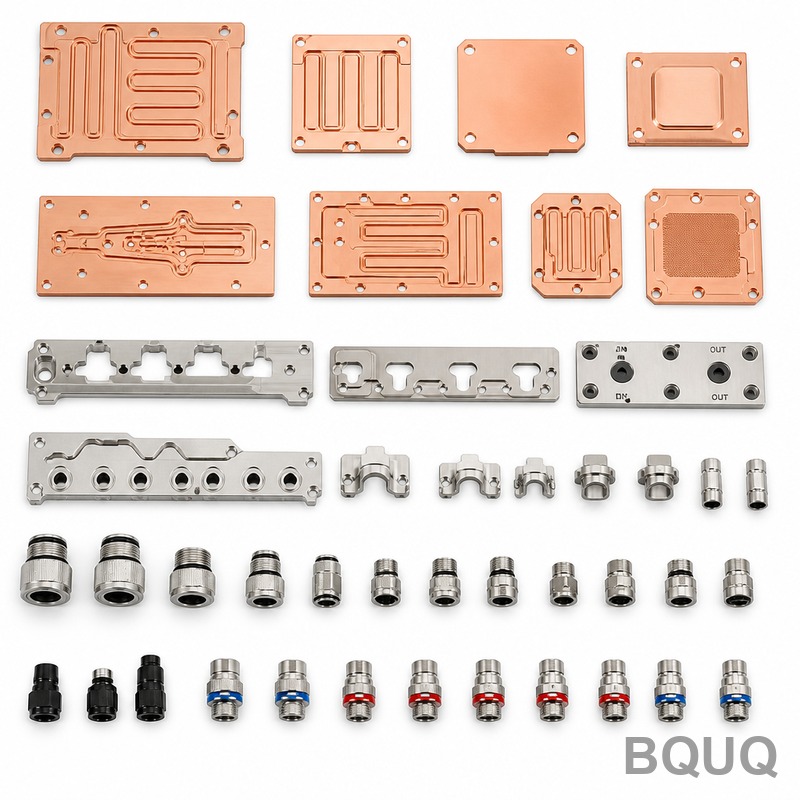
Cutting parameters are controlled via spindle load monitoring. For a typical aluminum mirror mount, we run a spindle speed of 15,000 RPM with a feed rate of 600 mm/min and a chip load of 0.02mm/tooth. This generates a cutting force that is constant and predictable, minimizing tool deflection. We also utilize diamond-tipped (PCD) inserts for aluminum finishing, which maintain their edge geometry for over 500 parts, ensuring consistent surface finish of Ra 0.1 to 0.2 micrometers. For hardened steel components (45 HRC and above), we switch to CBN (Cubic Boron Nitride) inserts and reduce speeds to prevent work-hardening.
Metrology and Environmental Control
Machining precision is meaningless without verification. Our inspection suite is calibrated to NIST standards. We use a Zeiss CMM with a stated accuracy of 1.2 micrometers for dimensional verification. However, the environment is the silent killer of accuracy. Our metrology lab is maintained at 20°C ± 0.5°C, with humidity controlled at 45% ± 5%. A 5°C drift in temperature can cause a 12-micrometer error on a 100mm steel part, completely invalidating a ±2 micrometer tolerance claim.
For surface finish, we use a Taylor Hobson profilometer. We measure Ra (Arithmetic Average) and Rz (Average Maximum Height). For precision bearing seats and optical reference surfaces, we specify Ra 0.05. This is achieved through a final precision lapping or polishing step, which is a separate process from milling or turning. We also use laser interferometry for checking linear displacement on large-axis parts, ensuring positioning accuracy of ±1 micrometer over a 500mm travel length.
Cost and Lead Time Analysis
Ultra-precision does not come at standard prices. The cost is driven by cycle time, inspection time, and scrap risk. A simple precision bracket (50x50x10mm) with ±5 micrometers tolerances might cost $150. However, a complex gimbal assembly with Invar components and ±2 micrometers tolerances can exceed $5,000. The inspection time on a CMM for a complex part can take up to 4 hours, which is often more expensive than the machining time itself.
| Complexity Level | Typical Tolerance | Part Size (mm) | Machining Time | Inspection Time | Unit Price (USD) | Lead Time |
| Cell1 | Cell2 | Cell3 | Cell4 | Cell5 | Cell6 | Cell7 |
| Standard Precision | ±5 µm | 50x50x10 | 45 min | 30 min | $120 - $180 | 5-7 days |
| High Precision | ±2 µm | 100x100x20 | 3 hours | 2 hours | $400 - $800 | 10-14 days |
| Ultra-Precision | ±1 µm | 150x150x30 | 8 hours | 4 hours | $1,500 - $3,500 | 15-20 days |
| Complex Assembly | ±2 µm (multi-axis) | 200x200x50 | 12 hours | 6 hours | $4,000 - $7,000 | 3-4 weeks |
FAQ-Style Tips for Design Engineers
**What is the realistic limit for a standard 3-axis CNC mill?** For a well-maintained machine in a temperature-controlled shop, a realistic holding tolerance is ±5 micrometers for features under 50mm in size. Below that, you enter the realm of jig grinding or lapping, which are separate processes.
**Should I specify GD&T (Geometric Dimensioning and Tolerancing) on my drawing?** Yes, absolutely. For scientific instruments, a flatness callout of 2 micrometers on a mounting face is more critical than a linear dimension. We use GD&T per ASME Y14.5-2018 to ensure that the datum features are defined, preventing ambiguity in how the part is measured and assembled.
**How does the surface finish affect the functional performance?** A poor surface finish on a kinematic mount can cause micro-slip and hysteresis. For a mirror mount, a Ra 0.4 finish might cause light scattering, reducing signal-to-noise ratio. We recommend specifying Ra 0.2 for general precision and Ra 0.05 for optical contact surfaces.
**What about coatings and plating?** Electroless nickel plating is common for aluminum to provide a hard, wear-resistant surface. However, the plating process (at ~90°C) can alter the base metal dimensions. We typically machine the part to final size, then apply a "build-up" allowance of 25-50 micrometers for the plating, and then perform a final precision grind or lapping to achieve the final tolerance.
Process Verification: Beyond the CMM
While the CMM provides dimensional data, it does not validate internal integrity. For critical components, we recommend a 100% inspection protocol. This includes a first article inspection (FAI) report that documents every dimension on the drawing. We also utilize white light interferometry for surface topography on optical components, which provides a 3D map of the surface, revealing waviness that a simple Ra value would miss. For parts subject to cyclic loading, we can perform X-ray inspection to check for internal voids in the stock material.
Conclusion and Recommendations
For ultra-precision scientific instrument components, the path to success is defined by three pillars: material science, environmental control, and metrology rigor. Do not attempt to cut corners on inspection time or temperature control; these are the hidden costs that ensure the part works as a system, not just as a standalone piece of metal. We recommend providing us with your full assembly drawing, not just the component print, so we can understand the functional requirements. This allows our process engineers to suggest the optimal datum structure and material for your specific application.
At BQUQ, we combine 20 years of manufacturing expertise with a modern, temperature-controlled facility to deliver components that meet the most demanding scientific specifications. We are ready to put our engineering team to work on your next project. For a detailed quote and a free manufacturability review, contact us. We provide 12-hour quoting for most inquiries.
Email: sc@bquq.com WhatsApp: +86 13713157787 www.bquq.com
Related Articles
- When CNC 'Speaks' — Intelligent Process Planning Driven by Large Models and Knowledge Graphs
- Digital twin-driven CNC machining: from simulation to closed-loop process optimization
- Analysis of the core technology of five-axis linkage machining: from motion to high-precision curved surface manufacturing
Frequently Asked Questions
What tolerances and surface finishes can you achieve for scientific instrument components?
We achieve tolerances of ±1 to ±3 micrometers and surface finishes below Ra 0.2 for scientific instrument components. This precision is maintained through a holistic engineering approach that includes material selection, thermal management, specialized tooling, and rigorous metrology, not just advanced CNC machines.
Which materials do you recommend for high-stability optical or vacuum components?
For optical mounts and vacuum components, we recommend Aluminum 5083 or 6061-T6 with a specific stress-relieving process, including cryogenic treatment, to reduce residual stress. For higher thermal stability, Titanium Grade 5 (Ti-6Al-4V) or Invar 36 are common, with Invar 36 offering a CTE of 1.2 x 10^-6 /°C versus aluminum's 23.6 x 10^-6 /°C.
How do you control thermal expansion in parts for laser interferometers?
We control thermal expansion by selecting materials with low CTE, such as Invar 36 (1.2 x 10^-6 /°C). For a 100mm aluminum part, a 1°C shift causes a 0.5 micrometer error, but only 0.12 micrometers in Invar. This performance justifies Invar's 15-20x higher raw material cost in high-stability environments.
What machining strategy do you use to hold ±2 micrometer tolerances?
We use a 'rough-finish-temper' protocol: roughing removes 70% of stock leaving 0.5mm, then a stress-relief cycle (e.g., 2 hours at 150°C for aluminum), followed by a semi-finish pass leaving 0.1mm, and a final finishing pass with a depth of cut between 0.01mm and 0.02mm. Spindle load monitoring controls cutting parameters, e.g., 15,000 RPM for aluminum.


