
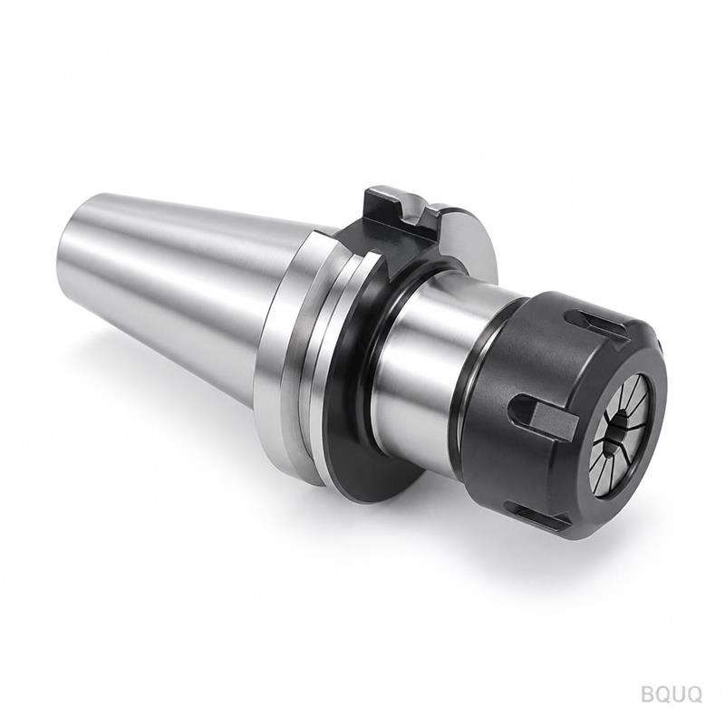
CNC Machining Copper: Tooling and Chip Control
Short answer: Copper machines fast but punishes lazy setups. Run uncoated or polished carbide at 150–300 m/min surface speed for pure copper, keep feed per tooth at 0.05–0.15 mm, and use high-pressure coolant with sharp, high-rake geometry. The real failure modes are built-up edge, gummy birds-nest chips, and thermal growth on thin walls — not tool wear. On a rigid machine with proper chip evacuation, copper holds ±0.005 mm tolerances as easily as brass, and BQUQ quotes copper CNC parts in 12 working hours.
Copper sits in an awkward spot for machinists. It is soft enough to weld itself to a cutting edge, ductile enough to produce long stringy chips that wrap around the tool holder, and thermally conductive enough that heat leaves the shear zone and soaks into the part and the fixture. None of these problems show up in a tool catalog. They show up on the shop floor, usually at 2 a.m., as a scrapped batch of busbars.
This article covers what actually matters when you put copper on a CNC: which alloys behave how, which tool geometries survive, how to break a chip that does not want to break, and where the process limits sit for tight-tolerance work.
Why is copper harder to machine than its hardness suggests?
Pure copper (C11000, ETP) has a Brinell hardness around 45–50 HB — softer than most aluminum alloys. By hardness alone it should cut like butter. It does not, for three reasons.
First, ductility. Copper elongates 40–50% before fracture. A chip does not shear off cleanly; it extrudes, stretches, and forms a continuous ribbon that carries heat away from the cut but tangles around everything in its path.
Second, adhesion. Copper has a strong affinity for cobalt and tungsten carbide binders. At the temperatures generated in the shear zone, copper micro-welds to the rake face, forming a built-up edge (BUE). The BUE grows, breaks off, takes a piece of the tool coating with it, and leaves a torn surface finish behind.
Third, thermal conductivity. Copper conducts heat at roughly 390 W/m·K, about 25 times better than stainless steel. That sounds helpful, but it means the heat you generate goes into the workpiece and the tool holder rather than into the chip. Thin-wall parts grow, fixtures creep, and dimensions drift across a batch.
The practical consequence: copper rewards sharp edges, generous rake angles, and aggressive chip evacuation far more than it rewards exotic tool materials.
Which copper alloys behave differently on a CNC?
Not all copper is the same problem. The alloy family changes the strategy more than any other variable.
| Alloy | Typical UNS | Machinability vs. C360 brass | Main issue | Typical use |
|---|---|---|---|---|
| Electrolytic tough pitch copper | C11000 | ~20% | Gummy chips, BUE, long stringers | Busbars, electrodes, gaskets |
| Oxygen-free copper | C10100 / C10200 | ~20% | Same as C11000, no hydrogen embrittlement risk | Vacuum, RF, high-conductivity parts |
| Tellurium copper | C14500 | ~80–90% | Brittle chips, excellent finish | Electrical connectors, weld tips |
| Beryllium copper | C17200 | ~40–50% (aged) | Beryllium dust hazard, needs containment | Springs, non-sparking tooling |
| Phosphor bronze | C51000 | ~60% | Moderate stringers | Bearings, bushings, springs |
| Naval brass | C46400 | ~90% | Low | Marine hardware |
| Free-cutting brass | C36000 | 100% (reference) | Zinc fume at high temp | General turned parts |
The takeaway: if your design allows it, tellurium copper (C14500) machines almost like brass while retaining roughly 93% IACS conductivity. If you need maximum conductivity, you are stuck with C11000 and must design the process around chip control. Beryllium copper adds a health-and-safety dimension — beryllium-bearing dust requires coolant flushing and containment, and many shops quote it at a premium for that reason alone.
What tooling actually works on copper?
Tool selection for copper is counterintuitive. Coatings that shine on steel often hurt here.
Substrate and coating
Use uncoated, fine-grain carbide with a polished rake face as the default. Polished surfaces reduce friction and adhesion, which is exactly what copper needs. If you must coat, choose a thin PVD coating with low affinity for copper — TiB₂ or a smooth diamond-like carbon (DLC) layer works better than TiAlN, which tends to promote BUE at lower speeds.
For pure copper at high volume, polycrystalline diamond (PCD) is the premium answer. PCD has extremely low friction against copper, resists adhesion, and holds an edge for hundreds of thousands of parts. The trade-off is cost and the fact that PCD cannot be resharpened into complex profiles easily.
Geometry
| Parameter | Recommended for pure copper | Recommended for brass / Te-Cu |
|---|---|---|
| Rake angle | 15–25° positive | 8–15° positive |
| Relief angle | 8–12° | 6–10° |
| Edge prep | Sharp, minimal hone (5–10 µm) | Light hone acceptable |
| Helix angle (end mill) | 35–45° | 30–40° |
| Flute count | 2–3 for roughing, 3–4 for finishing | 3–4 |
| Corner radius | 0.2–0.8 mm | 0.1–0.4 mm |
Sharp edges matter more than anything else. A honed edge that survives in steel will rub in copper, generate heat, and produce a work-hardened surface layer that makes the next pass worse.
Workholding
Copper's softness means standard hardened jaws will mar it. Use aluminum or brass soft jaws, or better, machined-on-site jaws that match the part profile. For thin-walled copper parts, vacuum fixturing or a low-melt wax pot eliminates clamping distortion entirely — the same principle covered in CNC vacuum fixtures. Collet chucks with a full 360° grip are preferable to three-jaw chucks for turned copper parts, because point contact deforms the workpiece.
How do you control chips in copper?
Chip control is the single biggest determinant of whether a copper job runs smoothly or becomes a scrap generator. Long stringy chips wrap around the tool, scratch finished surfaces, and can pull a part out of the fixture.
The four levers
1. Feed per tooth. Push it up. In copper, light feeds produce rubbing and work hardening; heavier feeds produce a thicker chip that breaks more readily. Aim for 0.05–0.15 mm/tooth on milling, 0.1–0.3 mm/rev on turning.
2. Depth of cut. Take a real cut, not a skimming pass. Radial engagement of 30–50% of tool diameter for roughing gives the chip somewhere to go.
3. Coolant delivery. High-pressure through-spindle coolant (40–70 bar where available) blasts chips out of the pocket and cools the shear zone. Flood coolant alone often leaves chips recirculating in the cut.
4. Interrupted cuts. Where the geometry allows, a pecking or oscillating toolpath breaks the chip mechanically. Some CAM systems offer "chip breaking" cycles for exactly this reason.
Chip forms and what they tell you
| Chip form | What it means | Corrective action |
|---|---|---|
| Long, tight spiral, no color | Feed too light, speed high | Increase feed per tooth |
| Long, straight ribbon | Insufficient chip breaker | Change insert geometry, add oscillation |
| Short, comma-shaped, straw color | Ideal | Maintain parameters |
| Fine powder / dust | Feed too heavy or tool dull | Reduce feed, inspect edge |
| Blue or black chips | Excessive speed, heat in cut | Reduce surface speed, increase coolant |
| Welded clumps on edge | Built-up edge forming | Increase speed slightly, polish rake face |
That last row is the counterintuitive one: when BUE forms, the usual fix is to increase cutting speed, not decrease it. Running below the BUE formation range keeps the shear zone hot enough that adhesion does not have time to establish.
What speeds and feeds should you start from?
These are starting points for uncoated carbide in a rigid setup, not gospel. Every machine, holder, and part geometry shifts the window.
| Operation | Material | Surface speed (m/min) | Feed | Notes |
|---|---|---|---|---|
| Face milling | C11000 | 200–300 | 0.08–0.15 mm/tooth | 3-flute, 45° helix |
| Pocketing | C11000 | 150–250 | 0.06–0.12 mm/tooth | Through-spindle coolant essential |
| Turning (rough) | C11000 | 180–280 | 0.15–0.3 mm/rev | Positive insert, sharp edge |
| Turning (finish) | C11000 | 250–350 | 0.05–0.1 mm/rev | Wiper geometry for Ra 0.4 |
| Drilling | C11000 | 60–100 | 0.1–0.2 mm/rev | 118–135° point, polished flutes |
| Milling | C14500 | 250–400 | 0.1–0.2 mm/tooth | Behaves like brass |
| Milling | C17200 (aged) | 100–180 | 0.08–0.12 mm/tooth | Containment required |
For a broader framework on how to dial in parameters across materials, see the CNC speeds and feeds guide.
How do you hold tight tolerances in copper?
Copper's thermal conductivity is a gift for electrical performance and a curse for metrology. A part that measures 50.000 mm off the machine may measure 49.985 mm after it cools.
Three practices make the difference:
- Control the thermal environment. Run coolant at a stable temperature, and let parts equalize before final inspection. For ±0.005 mm work, a 5 °C temperature swing on a 100 mm copper part moves roughly 8.5 µm — more than your entire tolerance.
- Separate roughing and finishing. Rough with stock left on, let the part relax, then finish. Copper work-hardens at the surface, and a single heavy pass leaves residual stress that springs the part after unclamping.
- Inspect in the same conditions as machining. A part measured in a 20 °C inspection room after machining in a 28 °C shop will not agree with the machine's probe.
BQUQ runs copper work on the same four production lines used for aluminum, brass, and stainless, with ±0.005 mm capability on CNC machining and turning. Because the shop is a single Dongguan facility rather than a broker network, process changes for copper — tool swaps, coolant pressure, fixturing — happen without a supply-chain handoff.
When should you redesign the copper part instead?
Sometimes the right answer is not a better toolpath but a different geometry. Copper is expensive per kilogram and slow to machine, so DFM changes pay back fast.
Common wins:
- Replace a deep pocket with a shallower one plus a separate cover plate. Deep pockets in gummy copper are where chips go to die.
- Convert a sharp internal corner to a corner radius matched to your smallest end mill. This eliminates a slow, chatter-prone operation.
- Specify C14500 instead of C11000 where conductivity allows. The machinability jump from ~20% to ~85% can cut cycle time by more than half.
- Tolerances only where they matter. A ±0.005 mm callout on a non-functional surface adds cost with no benefit. The DFM redesign examples article walks through how these decisions change quoted price.
Cost reduction in copper usually comes from three places: alloy substitution, geometry simplification, and chip-control-driven cycle time. The CNC machining cost reduction guide covers the full list.
Frequently Asked Questions
Q: Can copper be CNC machined to ±0.005 mm tolerances?
A: Yes, with caveats. Pure copper can hold ±0.005 mm on rigid machines with temperature-stable coolant and proper fixturing, but thermal expansion is the limiting factor, not the cutting process. A 100 mm copper part grows roughly 1.7 µm per °C. For tight-tolerance work, control the shop temperature, let parts equalize before inspection, and avoid single-pass finishing on thin walls.
Q: What is the best tool coating for machining copper?
A: Uncoated, polished fine-grain carbide is the default and often the best choice, because coatings can increase adhesion and promote built-up edge. If a coating is needed for edge life, thin PVD layers such as TiB₂ or DLC outperform TiAlN. For high-volume production, polycrystalline diamond (PCD) offers the lowest friction and longest life against copper, at higher tool cost.
Q: Why do my copper chips wrap around the tool instead of breaking?
A: Copper's high ductility means chips extrude rather than shear. The fix is almost always to increase feed per tooth (0.05–0.15 mm range), take a deeper radial engagement, and use high-pressure through-spindle coolant. Programmed chip-breaking cycles or oscillating toolpaths also help. Reducing feed makes the problem worse, not better, because light cuts rub and work-harden the surface.
Q: Is tellurium copper worth the extra cost over pure copper?
A: Usually yes for machined parts. C14500 machines at roughly 80–90% of free-cutting brass versus about 20% for C11000, which can cut cycle time by more than half. It retains around 93% IACS conductivity, so most electrical applications still qualify. If your design needs absolute maximum conductivity, stay with C11000 and accept the slower process.
Q: Does copper require special coolant or safety controls?
A: Standard water-soluble coolant works for most copper alloys, though it should be kept clean and at stable concentration to avoid staining. Beryllium copper (C17200) is the exception: beryllium-bearing dust and mist require containment, filtration, and personal protective equipment. Many shops quote C17200 at a premium for that reason, and it should never be machined dry.
Related Resources
- About BQUQ and our Dongguan factory: /about/
- CNC machining services: /cnc-machining/
- CNC turning parts: /cnc-turning-parts/
- CNC milling parts: /cnc-milling-parts/
- Industry trends: /industry-dynamics/
- Technical articles: /bquq-blog/
- FAQ: /faq/
- Contact us for a 12-hour quote: /contact/
Authored by the BQUQ Engineering Team. BQUQ (Dongguan) runs CNC machining (±0.005 mm), metal stamping, custom springs, and heat sink production in one ISO9001 factory. Source-direct from Dongguan, China — quote in 12 hours: sc@bquq.com | WhatsApp +86 13713157787 | www.bquq.com


