
Managing CNC Tool Wear: Cost and Tolerance
Short answer: CNC tool wear is a controllable cost, not an unavoidable one. In a typical aluminum job, one worn Ø10 mm carbide end mill can push a bore 0.02–0.04 mm oversize and scrap a part worth several times the tool's price. The fix is a three-part system: define a wear limit tied to your tolerance (usually 20–30% of the total band), measure it on a fixed interval, and change tools on a count or time trigger before the limit is reached. At BQUQ, an ISO9001 factory in Dongguan running four production lines, we hold ±0.005 mm on CNC work by treating tool life as a process parameter, not a maintenance afterthought. Quotes come back in 12 working hours.
Why does tool wear matter more than most buyers expect?
Tool wear is silent. A machine does not stop when an edge dulls; it keeps cutting, and every part after that point drifts a little further from nominal. On a ±0.05 mm feature that drift is invisible. On a ±0.01 mm feature it is the difference between a shipped lot and a rejected one.
Three failure modes matter to buyers:
- Dimensional drift. Flank wear increases cutting forces and pushes the tool away from the workpiece, so bores run small and slots run narrow — or, with thermal growth, the opposite. Direction depends on the operation, but the magnitude is predictable.
- Surface finish degradation. A worn edge rubs instead of shears. Ra values climb, and on aluminum you get built-up edge and smeared material.
- Burr formation. Dull tools push material rather than cut it, producing heavier burrs that need more deburring labor — a hidden cost that lands on the supplier and eventually on your price.
The cost of wear is not the tool. It is the scrap, the rework, the inspection time, and the schedule disruption. A $30 end mill that causes two scrapped parts at $40 each has already cost more than the tool.
How does tool wear translate into tolerance drift?
Think of the tolerance band as a budget. Part of that budget goes to machine positioning, part to thermal effects, part to fixturing, and part to tool wear. If wear consumes 60% of the band, you have no room left for anything else.
| Tolerance band | Suggested wear allowance | Practical trigger |
|---|---|---|
| ±0.100 mm | 0.040–0.050 mm | Change at shift end or 300+ min cut time |
| ±0.050 mm | 0.020–0.025 mm | Change at 120–180 min cut time |
| ±0.020 mm | 0.008–0.010 mm | Change at 60–90 min cut time |
| ±0.010 mm | 0.004–0.005 mm | Change at 30–45 min, verify with in-process gauging |
| ±0.005 mm | 0.002–0.003 mm | Change per part-lot, offset-compensate every few parts |
These figures are indicative and depend on material, coating, coolant, and rigidity. The principle holds: the tighter the band, the smaller the wear allowance, and the more frequently you must intervene.
For a deeper look at how individual tolerances accumulate into a stack-up problem, see how tolerance stack-up decides assembly fit.
The offset-compensation shortcut
You do not always have to change the tool. Modern controls let an operator measure a feature and adjust the tool offset to compensate for wear. This extends tool life substantially — often 2–3× — but it has a limit. Once flank wear passes roughly 0.15–0.20 mm on a carbide edge, the tool stops cutting cleanly and compensation only masks the problem while finish and burr quality collapse. Compensation buys time; it does not replace the change.
What actually drives tool wear rate?
Wear is not random. It responds to a small set of variables you can control.
Cutting speed
Speed is the dominant lever. Doubling surface speed can cut tool life by 50–80% depending on the material. This is why the same end mill lasts all week in 6061 aluminum and a few hours in 304 stainless.
Material and hardness
| Work material | Relative wear rate | Typical notes |
|---|---|---|
| 6061 / 6082 aluminum | Low | Long life, watch built-up edge |
| Brass, copper alloys | Low–medium | Abrasive in free-machining grades |
| 304 / 316 stainless | High | Work hardening accelerates wear |
| 4140 / tool steel (pre-hard) | High | Reduce speed, increase feed |
| Titanium alloys | Very high | Heat concentration at the edge |
| Glass-filled plastics | Medium–high | Abrasive fillers |
Coating and geometry
TiAlN and AlTiN coatings extend life in steel and stainless; uncoated polished carbide is often better in aluminum because it resists built-up edge. A coating chosen for the wrong material can shorten life rather than extend it.
Coolant and chip evacuation
Recutting chips is one of the fastest ways to destroy an edge. High-pressure through-tool coolant and correct chip load matter more than most operators assume.
Rigidity
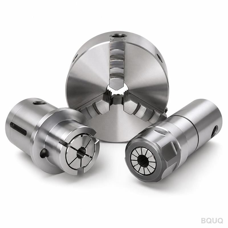
A tool holder with excessive runout loads one flute harder than the others. On a four-flute cutter, 0.02 mm of runout can halve effective life. This is one reason we treat workholding and tool holding as part of the wear strategy — the same logic behind soft jaws and repeatable workholding.
How do you monitor tool wear without stopping the machine?
There are four practical levels, and most shops should use at least two.
1. Count-based replacement. Change the tool after N parts or N minutes of cut time. Simple, cheap, and effective if your baseline is set from real data. The risk is that it ignores material variation between lots.
2. Periodic dimensional checks. Measure a critical feature every 10–20 parts with a micrometer or bore gauge and watch the trend. When the trend line approaches the wear allowance, change the tool.
3. Spindle load and power monitoring. Modern controls log spindle load. A gradual rise at constant parameters signals wear. This catches problems between dimensional checks.
4. In-process probing or laser tool setting. The most accurate option. A laser tool setter measures actual tool length and diameter before each cycle and updates offsets automatically. Best suited to high-mix, tight-tolerance work.
| Method | Setup cost | Accuracy | Best fit |
|---|---|---|---|
| Count-based | Very low | Low | Stable, high-volume runs |
| Periodic gauging | Low | Medium–high | General job shop |
| Spindle load monitoring | Medium | Medium | Lights-out or unattended runs |
| Laser tool setter / probing | High | Very high | ±0.005 mm work, high mix |
For shops verifying wear-driven drift, the choice of measurement tool matters too — see CMM versus hand tools for inspection.
What does tool wear actually cost per part?
This is where the argument usually gets won. Tool cost per part is small; the consequences of ignoring wear are not.
| Cost element | Typical magnitude | Notes |
|---|---|---|
| Tool purchase | $0.05–$1.50 per part | Depends on cycle time and tool price |
| Tool change downtime | $0.20–$2.00 per part | 1–3 min per change, machine rate applies |
| Scrap from drift | $0–$15 per part | Highly variable; the real risk |
| Extra inspection | $0.30–$3.00 per part | Rises as capability drops |
| Extra deburring | $0.20–$2.50 per part | Dull tools create heavier burrs |
The pattern is consistent: a disciplined tool-change program costs cents, while a reactive one costs dollars. This is one of the largest single levers in CNC machining cost reduction, and it is almost entirely within the supplier's control.
The hidden cost of over-changing
There is a counter-pressure. Changing tools too often wastes spindle time and money. The optimum is not "change as often as possible" — it is "change at the point where the marginal cost of the next part's risk exceeds the cost of the change." For most ±0.05 mm work, that point is well before the tool looks dull.
What should buyers specify to control tool wear risk?
You do not need to micromanage your supplier's tool crib. You do need to remove ambiguity.
- State the tolerance and the feature that matters. "±0.02 mm on the bearing bore" tells the supplier where to spend tool life budget.
- State the inspection method and sampling plan. If you require 100% bore gauging, the supplier will plan tool changes around it.
- Ask about capability, not just conformance. A Cpk figure on the critical feature tells you whether the process is stable or just lucky.
- Flag material and lot variation. If your castings vary in hardness, say so — it changes wear rate.
- Agree on what happens at the wear limit. Predefined triggers avoid arguments during production.
At BQUQ we run CNC machining to ±0.005 mm on qualifying features, with tool life managed per job rather than per operator habit. Flexible MOQ means prototype lots get the same wear discipline as production runs — a prototype with a drifted bore teaches you nothing.
Frequently Asked Questions
Q: How often should CNC tools be changed?
A: It depends entirely on the tolerance and material. For ±0.05 mm aluminum work, a 120–180 minute cut-time interval is a reasonable starting point. For ±0.010 mm work, 30–45 minutes with dimensional verification is safer. The correct method is to set an initial interval from tool supplier data, then adjust it using measured drift on your own parts. Never rely on a generic schedule copied from another shop.
Q: Can tool wear be compensated instead of changing the tool?
A: Yes, up to a point. Offset compensation adjusts the control to account for a worn edge and can extend usable life by 2–3×. However, once flank wear exceeds roughly 0.15–0.20 mm on carbide, surface finish and burr formation degrade even if dimensions stay in tolerance. Compensation is a bridge between changes, not a replacement for them.
Q: Does tool wear affect surface finish as much as dimensions?
A: Often more. Dimensional drift is gradual and measurable; finish degradation can appear suddenly when a coating breaks down or built-up edge forms. On aluminum, a worn edge smears material and raises Ra noticeably. If your drawing specifies a finish callout, tool wear is a finish control issue, not just a dimensional one.
Q: What is the biggest cause of premature tool wear?
A: Excessive cutting speed and poor chip evacuation, in that order. Running a tool 30% too fast can cut life by half. Recutting chips — common with insufficient coolant pressure or wrong flute count — damages the edge almost as fast. Tool holder runout is a close third, since it loads one flute disproportionately.
Q: How do I audit a supplier's tool wear management?
A: Ask three questions: what is the wear allowance for this tolerance, how is it measured, and what triggers a change. A supplier with a real system answers immediately with numbers. A supplier without one gives a general answer about experienced operators. Also ask whether they log tool changes per job — records are the clearest evidence of a managed process.
Related Resources
- Learn how BQUQ approaches CNC machining across four production lines in one Dongguan factory
- Review CNC milling parts capabilities and tolerance ranges
- Compare CNC turning parts for round-feature wear control
- Read about our ISO9001 quality system and factory profile
- Browse more technical articles on CNC process control
- See industry trends in precision manufacturing
- Check the FAQ or contact our engineering team for a quote in 12 working hours
Authored by the BQUQ Engineering Team. BQUQ (Dongguan) runs CNC machining (±0.005 mm), metal stamping, custom springs, and heat sink production in one ISO9001 factory. Source-direct from Dongguan, China — quote in 12 hours: sc@bquq.com | WhatsApp +86 13713157787 | www.bquq.com


