
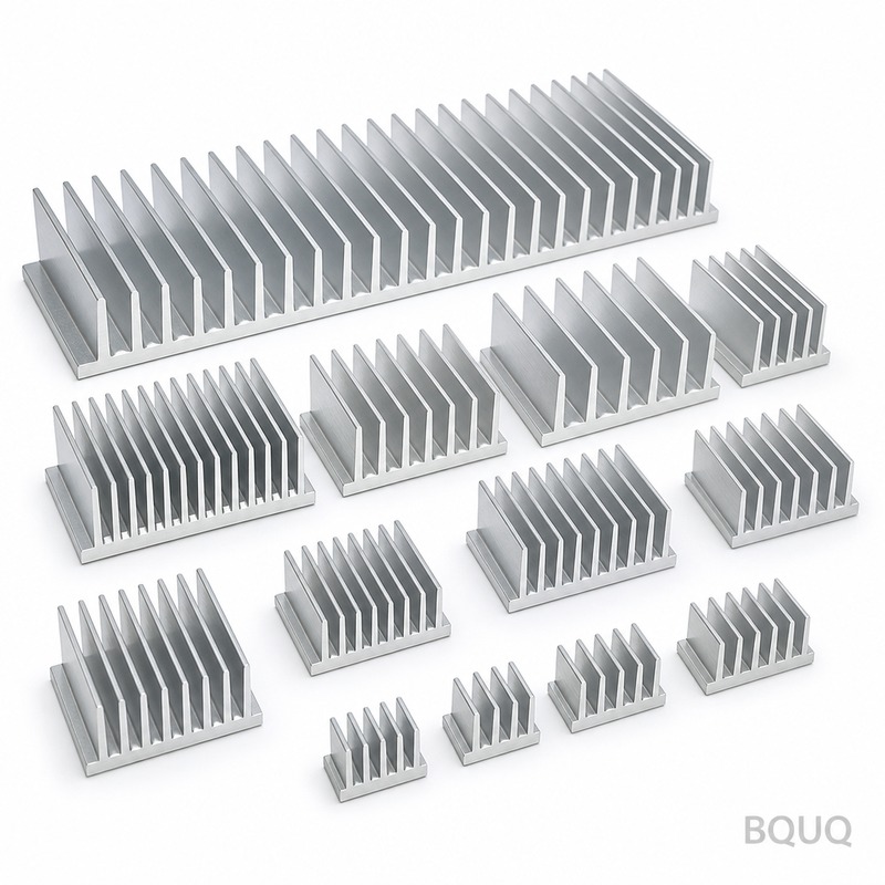
Heat Sink Design for Forced Airflow: Ducting and Bypass
Short answer: In forced-airflow systems, the fin stack only cools what passes through it. If 40% of the fan's air bypasses over or around the sink, you lose roughly 40% of the convective capacity regardless of how good the extrusion is. Design the duct first, then the fins: target a duct that seals the fin tips to within 1–2 mm, keep bypass leakage under about 10% of total flow, and size fin density so face velocity stays in the 3–6 m/s band. BQUQ machines and extrudes these heat sinks in one Dongguan ISO9001 factory and quotes in 12 working hours.
Why does bypass air quietly destroy heat sink performance?
A heat sink is a flow device before it is a thermal device. Every watt it removes has to be carried away by a mass of air that physically touches fin surfaces. Air, like water, takes the path of least resistance — and a bare fin stack sitting in a plenum is a high-resistance path compared to the open space above it.
This is the bypass problem. In a typical enclosure, the fan pressurizes a chamber. Air can either squeeze between the fins (useful) or spill over the top of the fin tips, around the sides, or through the gaps between the heat sink base and the PCB (useless). The ratio between those two flows is set almost entirely by geometry, not by fan power. Doubling fan speed raises both flows proportionally, so the fraction of useful air barely changes.
Practically, engineers see this as a stubborn temperature plateau. They swap in a stronger fan, the noise goes up, the case temperature drops a couple of degrees, and the junction temperature refuses to move. The extrusion is not the bottleneck. The air path is.
The fix is not a denser fin stack. It is a duct that converts an open plenum into a channel, so the pressure drop across the fins is the only path available to the air.
How much air is actually reaching your fins?
You can estimate this before you cut metal. The useful metric is face velocity — the average speed of air entering the fin channels, not the fan's free-delivery rating.
| Fan nominal airflow | Open plenum, no duct | Loose shroud, 5 mm gaps | Sealed duct, ≤1 mm gaps |
|---|---|---|---|
| 20 CFM | ~45% through fins | ~70% through fins | ~92% through fins |
| 50 CFM | ~40% through fins | ~68% through fins | ~90% through fins |
| 100 CFM | ~35% through fins | ~65% through fins | ~88% through fins |
Figures are typical and indicative for a 40 × 40 mm fin stack in a 120 mm enclosure; measure your own case. The trend is what matters: the larger the fan, the worse an open plenum behaves, because the bypass path grows faster than the fin channel capacity.
A second-order effect matters too. Bypass air is not just wasted — it is short-circuited. It recirculates hot exhaust back into the intake zone, raising the inlet air temperature the fins see. A 5 °C rise in local ambient costs you roughly 5 °C at the junction, which is often the entire thermal margin.
Ducting rules that hold up in production
Seal the fin tips, not the whole sink
The single highest-value duct feature is a shroud that touches or nearly touches the fin tips. A 1–2 mm tip clearance is a reasonable production target: tight enough to suppress leakage, loose enough to survive extrusion tolerance, anodizing thickness, and assembly stack-up. Below 1 mm you start paying for it in scrap and rework.
Duct the inlet as well as the outlet
Many designs shroud the exhaust side only. That still leaves the inlet drawing from a low-resistance plenum. A full inlet-to-outlet duct — often a single molded or stamped shell — is roughly twice as effective as an exhaust-only shroud at the same material cost.
Keep the duct cross-section constant
A duct that necks down before the fins raises velocity but also raises pressure drop, and the fan moves less air. For most axial fans, a constant-area duct with a short rounded inlet bell is the better trade. Reserve converging ducts for blowers, which handle static pressure far better.
Respect the fan's dead zone
Axial fans have a low-velocity hub region and corner losses. If the duct inlet sits directly on the fan, the hub shadow lands on the center of your fin stack. Offset the sink, add a short plenum gap of 5–10 mm, or accept that the center fins run hotter and design the base thickness accordingly.
Fin density, pressure drop, and the bypass trade
Fin density is where ducting and thermal design meet. Tight fins increase surface area but also increase pressure drop, which pushes more air into the bypass path — unless the duct is sealed.
| Fin pitch | Fins per 40 mm | Typical face velocity | Pressure drop | Notes |
|---|---|---|---|---|
| 2.0 mm | 20 | 3–6 m/s | Low | Forgiving; good with weak fans |
| 1.5 mm | 26 | 3–5 m/s | Moderate | Common sweet spot for ducted sinks |
| 1.0 mm | 40 | 2–4 m/s | High | Needs sealed duct and a pressure-capable fan |
| 0.6 mm | 66 | 1.5–3 m/s | Very high | Skived or bonded fin; blower territory |
Values are indicative for 25–40 mm tall aluminum fins. The rule of thumb: as fin pitch tightens, the duct must get better, not just the fan. A 1.0 mm pitch extrusion in an open plenum frequently underperforms a 2.0 mm pitch extrusion in a sealed duct, at higher cost.
When to switch fin technologies
Extruded profiles handle pitches down to roughly 1.0–1.5 mm well and are the cheapest per unit at volume. Below that, extrusion dies become fragile and yield drops. At that point, consider skived or bonded-fin construction or a vapor chamber base for high-flux devices. If your budget is the binding constraint rather than the pitch, our notes on cost reduction without losing thermal margin cover where material can be removed safely.
A worked example: 150 W power supply module
Consider a 150 W module with a 60 × 60 mm footprint, an 80 mm axial fan at 40 CFM, and a target case-to-ambient rise of 25 °C.
1. Baseline, no duct. Roughly 40% of the airflow crosses the fins. Effective flow ≈ 16 CFM. Measured rise lands near 38 °C — over budget.
2. Add a sealed shroud. Effective flow rises to about 36 CFM. Rise drops to roughly 24 °C. No change to the extrusion.
3. Then optimize the extrusion. With the duct in place, tightening pitch from 2.0 mm to 1.5 mm and adding 8 mm of fin height buys another 3–4 °C, because the extra pressure drop no longer pushes air into a bypass path.
The lesson generalizes: ducting first, extrusion second. Teams that reverse the order spend tooling money solving the wrong problem. This pattern shows up repeatedly in power supply and industrial module cooling, where enclosure geometry usually dominates the thermal result.
Manufacturing tolerances that affect duct fit
A duct only works if the parts it seals against are dimensionally predictable.
| Feature | Typical tolerance | Why it matters |
|---|---|---|
| Fin tip flatness | ±0.10 mm | Determines achievable tip clearance |
| Base flatness | ±0.05 mm | Contact with the device or TIM |
| Fin pitch | ±0.05 mm | Airflow distribution across the stack |
| Mounting hole position | ±0.10 mm | Duct and fan alignment |
| Overall height | ±0.15 mm | Duct ceiling clearance |
BQUQ holds ±0.005 mm on CNC-machined features where the interface demands it, and standard extrusion tolerances elsewhere — the point is to specify the tight tolerance only where the duct actually seals. Over-tolerancing fin tips across a 200 mm extrusion adds cost with no thermal return. Our CNC-machined heat sinks cover the machined-interface cases; extruded profiles handle the fin field.
Material and finish choices for ducted sinks
Once airflow is controlled, material selection becomes straightforward. Aluminum extrusion is the default for ducted forced-air sinks: light, cheap, and adequate for most flux densities under 50 W/cm² at the base. Copper bases or copper inserts help when the heat source is small and concentrated, since spreading resistance — not convection — is the limit.
Anodizing adds a thin oxide layer that slightly improves emissivity but does nothing meaningful in a ducted forced-convection path. Black anodizing is usually specified for appearance or corrosion resistance, not thermal gain. Keep the finish decision separate from the airflow decision.
FAQ
Q: How much bypass is acceptable in a forced-airflow heat sink?
A: Keep bypass leakage under roughly 10% of total fan flow for a well-behaved design. Above 20%, the fin stack is effectively decoupled from the fan and adding airflow buys very little. Measure by comparing inlet and outlet air temperatures across the sink: a small delta means most air is going around, not through.
Q: Does a duct always improve cooling?
A: No. A duct adds pressure drop, so a weak fan may move noticeably less air overall. Ducting pays off when the fan has static-pressure headroom and the plenum is large relative to the fin stack. If your fan is already at its pressure limit, a less restrictive fin pitch is the better first move.
Q: What fin pitch should I start with for forced air?
A: Start at 1.5 mm pitch for ducted designs and 2.0 mm for unducted or loosely shrouded ones. These are typical starting points, not rules. Then measure face velocity and iterate. Tighter pitches below 1.0 mm generally require a sealed duct and a blower rather than an axial fan.
Q: Can I 3D print the duct instead of tooling it?
A: Yes for prototypes and low volume, and it is a fast way to validate tip clearance and inlet geometry. For production, molded plastic or stamped sheet metal usually wins on cost and dimensional repeatability. Printed ducts can also creep or warp near hot exhaust zones, so verify at temperature.
Q: How do I know if my problem is the duct or the heat sink?
A: Run one test: temporarily seal the fin tips with tape or foam and re-measure. If temperatures drop sharply, the problem is bypass and the duct is the fix. If temperatures barely move, the fin stack, base spreading, or interface material is the limiting factor.
Related Resources
- About BQUQ and our Dongguan factory: /about/
- Full heat sink product range: /heat-sinks/
- Extruded aluminum heat sink profiles: /extruded-heat-sinks/
- Industry trends in thermal management: /industry-dynamics/
- Technical articles and design guides: /bquq-blog/
- Case studies: /case/
- Contact the engineering team: /contact/
Authored by the BQUQ Engineering Team. BQUQ (Dongguan) runs CNC machining (±0.005 mm), metal stamping, custom springs, and heat sink production in one ISO9001 factory. Source-direct from Dongguan, China — quote in 12 hours: sc@bquq.com | WhatsApp +86 13713157787 | www.bquq.com


