
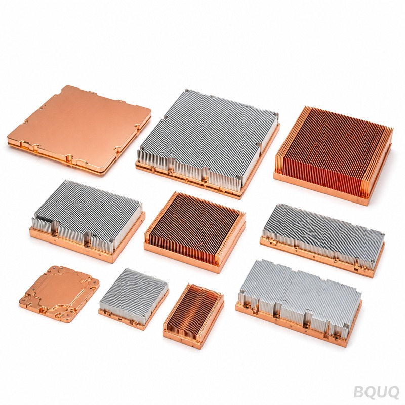
Skived Heat Sinks: Process, Fin Density and Cost
Short answer: Skiving is a metal-cutting process that peels fins up from a solid aluminum or copper block with a sharp blade, so the fins and base are one continuous piece of metal with no joint, no filler and no interface resistance. Typical skived fins run 0.4–1.0 mm thick at 0.8–2.0 mm pitch, giving roughly 2–4× the fin density of a comparable extrusion. For a 100 × 100 mm aluminum skived heat sink, tooling is usually zero, unit cost is typically 1.5–3× an extruded equivalent, and lead time from a Dongguan source factory such as BQUQ is commonly 7–15 days after drawing approval, with quotes returned in 12 working hours.
Skived heat sinks sit in a narrow band between extruded profiles and bonded-fin assemblies. They exist because of a simple physical limit: an extrusion die can only push metal through a gap so narrow before the tooling breaks or the profile tears. Skiving sidesteps that limit entirely by cutting fins from solid stock instead of squeezing them through a die.
This article covers how the skiving process actually works, what fin densities are realistic, where it beats extrusion and where it does not, and how cost is built up so you can make an informed sourcing decision.
What Is a Skived Heat Sink?
A skived heat sink is a monolithic heat sink whose fins are formed by a blade that shears and lifts metal from the surface of a solid block. Nothing is welded, soldered, epoxied or brazed. The fin and the base are the same continuous grain of aluminum or copper.
That continuity matters thermally. Every joint in a heat sink adds a thermal interface. Bonded-fin heat sinks use epoxy or solder between fin and base, and that layer has its own resistance plus a risk of voids. A skived fin has no such layer, so heat travels from the base into the fin with only bulk conduction losses.
The process is also flexible. Because there is no die, fin count, fin height, fin thickness and base thickness can all be changed between production runs without new tooling. For low-to-mid volume programs, or for designs still being thermally validated, that flexibility is often worth more than the lower unit cost of an extrusion.
Skiving vs. other fin-forming methods
| Method | Typical fin thickness | Typical fin density | Tooling cost | Joint resistance |
|---|---|---|---|---|
| Skiving | 0.4–1.0 mm | High | None to low | None (monolithic) |
| Aluminum extrusion | 1.0–3.0 mm | Low to medium | High (die) | None (monolithic) |
| Bonded / soldered fin | 0.3–1.0 mm | High | Low to medium | Present at each fin |
| Folded fin | 0.2–0.5 mm | Very high | Medium | Present at base joint |
| Die casting | 2.0–5.0 mm | Very low | High | None (monolithic) |
The table above is indicative and reflects common commercial ranges rather than fixed limits. Die casting, for example, is excellent for complex 3D geometry and mounting bosses, but poor at dense fins. Skiving is the opposite: simple geometry, dense fins.
How Does the Skiving Process Work?
Skiving is a controlled machining operation, usually run on a dedicated skiving machine or a heavily modified planer-type platform. The sequence is straightforward but unforgiving of setup error.
Step 1: Stock preparation
The process starts with a solid billet or plate of aluminum (typically 6061 or 6063) or copper (typically C11000). The block is faced and squared so the top surface is flat within a tight tolerance. Any bow in the stock will be reproduced in the fin tips, so this step sets the ceiling on final flatness.
Step 2: Blade setup and angle
A hardened skiving blade is set at a shallow angle to the work surface. The blade does not cut a chip away in the conventional milling sense — it shears a layer of metal and curls it upward. Blade angle, rake, edge sharpness and depth of cut together determine whether the fin stands up cleanly or tears.
Step 3: Successive passes
The tool advances by one fin pitch, shears the next fin, and repeats. Each pass lifts a fin and leaves a shallow groove in the base. The base thickness is therefore consumed progressively, which is why base thickness must be specified with the fin height in mind.
Step 4: Fin forming and straightening
Freshly skived fins are not perfectly straight. They are usually pressed or rolled to a consistent height and parallel alignment. This is where fin height tolerance is actually established, typically within ±0.05 mm to ±0.10 mm on well-controlled production.
Step 5: Secondary machining
The base is milled to final thickness, mounting holes are drilled and tapped, edges are chamfered, and any pocket for a heat pipe or component clearance is cut. At BQUQ this is done on the same CNC platform used for our CNC machined heat sinks, holding ±0.005 mm on critical features such as mounting hole position and base flatness.
Step 6: Surface finishing
Bare aluminum skived heat sinks are common. Black anodizing is often requested for appearance or emissivity, though at typical natural-convection conditions the radiation benefit is modest compared with conduction and convection. Copper skived parts are usually left bare or nickel-plated to prevent oxidation.
What Fin Density Can Skiving Actually Achieve?
Fin density is usually expressed as pitch (center-to-center spacing) or as fins per inch (FPI). Skiving routinely reaches 0.8–2.0 mm pitch, which is roughly 13–32 FPI. In production, a fin thickness of 0.5 mm with a 1.0 mm pitch is a very common, stable combination.
There is a trade-off triangle here that engineers should understand before specifying:
- Thinner fins increase surface area but reduce conduction along the fin, so the fin tip runs cooler than the base and contributes less than its area suggests.
- Tighter pitch increases area but restricts airflow. Below roughly 1 mm gap, dust fouling and pressure drop become real problems in forced-convection designs.
- Taller fins increase area but amplify tip temperature drop. Aspect ratios beyond about 15:1 (height to thickness) become difficult to keep straight and are prone to damage in handling.
| Parameter | Conservative | Typical production | Aggressive |
|---|---|---|---|
| Fin thickness | 0.8–1.0 mm | 0.4–0.6 mm | 0.3 mm |
| Fin pitch | 1.5–2.0 mm | 0.8–1.2 mm | 0.6 mm |
| Fin height | 10–25 mm | 25–50 mm | 50–80 mm |
| Fin height tolerance | ±0.10 mm | ±0.05 mm | ±0.03 mm |
| Base thickness | 5–10 mm | 3–6 mm | 2 mm |
Values in the "aggressive" column are achievable but should be validated with a thermal prototype before committing to volume. They also raise unit cost and reduce yield.
Skiving vs. Extrusion: When Should You Choose Which?
This is the single most common sourcing question, and the honest answer is that they solve different problems.
Choose extrusion when: your fin pitch is 2 mm or wider, your annual volume is high enough to amortize a die, your profile needs to be long and constant, and your thermal target is moderate. Extruded profiles are cheap at volume and available in enormous standard libraries. See our comparison in the heat sink design checklist.
Choose skiving when: you need fin pitch below about 1.5 mm, your volume is low to mid, your design is still changing, or you need a copper heat sink. Copper cannot be economically extruded into dense fin profiles, which is exactly why copper skived fin heat sinks dominate high-end applications.
Choose bonded fin when: you need fins taller than about 60 mm, or you need to mix materials, such as a copper base with aluminum fins.
A practical rule: if an extrusion can hit your thermal target with fins at 2 mm pitch or wider and your volume exceeds roughly 5,000 pieces per year, extrusion will usually be cheaper per unit. Below that, or below 1.5 mm pitch, skiving generally wins on total cost of ownership because there is no die to amortize.
What Drives Skived Heat Sink Cost?
Unit price for a skived heat sink is built from five components. Understanding them lets you target cost reduction intelligently rather than just asking for a discount.
| Cost driver | Share of unit cost (indicative) | How to reduce it |
|---|---|---|
| Raw material (Al or Cu) | 30–55% | Reduce base thickness; use aluminum where copper is not required |
| Machine time | 25–40% | Looser fin pitch, shorter fins, fewer passes |
| Secondary CNC | 10–20% | Simplify mounting features, reduce tapped holes |
| Finishing | 5–15% | Specify bare aluminum instead of anodized where acceptable |
| Yield / scrap | 5–15% | Avoid aggressive fin aspect ratios |
Copper is the dominant variable. Copper costs several times more per kilogram than aluminum and is roughly three times denser, so a copper skived heat sink can easily cost 3–5× an aluminum one of identical geometry. Only specify copper where the higher thermal conductivity is genuinely needed — typically in high heat flux applications above roughly 50 W/cm² at the source, or where spreading resistance in the base dominates.
Machine time scales with the number of fin passes. Doubling fin count roughly doubles skiving time, which is why aggressive fin densities carry a real cost penalty rather than being free surface area.
For a broader treatment of where money is typically wasted in a heat sink program, see heat sink cost reduction.
Design choices that quietly add cost
- Specifying anodizing on a part that will never be visible.
- Adding a tapped hole pattern that requires a separate fixturing setup.
- Requesting ±0.02 mm fin height tolerance when ±0.05 mm would pass thermal validation.
- Designing a fin height that forces two skiving passes instead of one.
- Mixing copper base with aluminum fins, which reintroduces a joint and defeats the purpose of skiving.
What Should Buyers Verify Before Ordering?
Skived heat sinks are easy to quote and harder to produce consistently. Before placing a production order, confirm the following with your supplier.
1. Base flatness after skiving. Skiving induces stress that can bow the base. Ask for a flatness value, typically 0.05–0.10 mm across the mounting face for a 100 mm part, and confirm it is measured after finishing, not before.
2. Fin tip condition. Look for burrs, tears or rolled-over tips. These reduce effective area and can short adjacent fins.
3. Fin height uniformity. Measure across the full fin array, not just the center. Edge fins often run tall or short.
4. Material certification. For aluminum, confirm alloy and temper. For copper, confirm conductivity grade.
5. Surface finish specification. Bare aluminum skived parts should be clearly defined — see heat sink anodizing and bare finish for how finish choice interacts with thermal performance and corrosion.
6. Sample-first policy. Always thermally test a prototype before tooling up or committing to volume. Skiving has no tooling to amortize, so sampling is cheap and fast.
BQUQ runs skived heat sink production alongside CNC machining, metal stamping and custom springs across four production lines in one Dongguan factory. That means the base machining, hole pattern and finishing for a skived heat sink are handled in the same facility as the skiving itself, which shortens the loop between first article and production. MOQ is flexible, and quotes come back within 12 working hours.
Frequently Asked Questions
Q: Can skived heat sinks be made from copper?
A: Yes. Copper skiving is common for high heat flux applications because copper's thermal conductivity is roughly twice that of aluminum. The trade-off is cost: copper is significantly more expensive per kilogram and about three times denser, so a copper skived heat sink typically costs several times an aluminum one of the same geometry. Specify copper only when base spreading resistance or flux density genuinely requires it.
Q: What is the minimum fin thickness for skiving?
A: In stable production, 0.4 mm is a realistic minimum for aluminum, and 0.5 mm is a safer default. Copper can sometimes be taken thinner because it is more ductile, but thin copper fins deform easily during handling. Fins below 0.4 mm are possible on a development basis but usually reduce yield enough to offset the thermal gain.
Q: Is skiving more expensive than extrusion?
A: Per unit at high volume, usually yes — typically 1.5 to 3 times an equivalent extrusion. But extrusion requires a die, which can cost thousands of dollars and takes weeks to cut. At low to mid volume, or when fin pitch must be below about 1.5 mm, skiving often has a lower total cost because there is no tooling to amortize and no die lead time.
Q: Do skived heat sinks need a thermal interface material?
A: Yes. The skived fin array is monolithic, but the heat sink still mounts to a component through a mechanical interface, and that interface needs a TIM. The choice of gap filler, phase-change pad or grease depends on surface flatness, mounting pressure and gap. See our guide to thermal interface selection for how to match TIM to a skived base.
Q: What lead time should I expect?
A: From a Dongguan source factory such as BQUQ, a quotation is typically returned within 12 working hours of receiving a drawing or 3D model. Prototype skived heat sinks commonly ship in 7–15 days after drawing approval, and production runs depend on quantity, finishing and material availability. Copper parts generally take longer than aluminum because of material lead time.
Related Resources
- About BQUQ and our four production lines in Dongguan: /about/
- Full heat sink product range, including skived, extruded and CNC machined: /heat-sinks/
- CNC machined heat sinks with ±0.005 mm tolerance: /cnc-machined-heat-sinks/
- Industry trends in thermal management and electronics cooling: /industry-dynamics/
- Technical articles and engineering guides: /bquq-blog/
- Frequently asked questions on sourcing and manufacturing: /faq/
- Case studies from BQUQ production programs: /case/
- Contact the engineering team for a 12-hour quote: /contact/
Authored by the BQUQ Engineering Team. BQUQ (Dongguan) runs CNC machining (±0.005 mm), metal stamping, custom springs, and heat sink production in one ISO9001 factory. Source-direct from Dongguan, China — quote in 12 hours: sc@bquq.com | WhatsApp +86 13713157787 | www.bquq.com


