
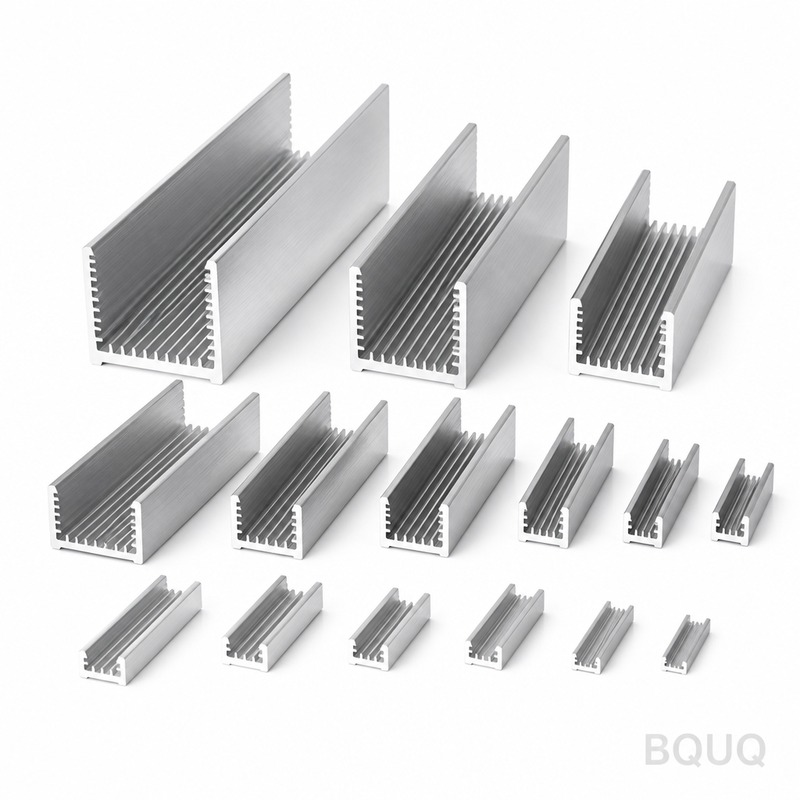
Soldering and Brazing Heat Sink Assemblies
Short answer: Soldering joins heat sink parts below roughly 450 °C with filler metals such as Sn-Ag-Cu or Sn-Sb alloys, while brazing uses filler metals above 450 °C, typically aluminium-silicon or silver-copper based. Both create a metallurgical bond that replaces a dry mechanical interface with a thermally conductive layer, often reducing joint resistance from several K·cm²/W to well under 0.5 K·cm²/W. Choose soldering for copper fins, plated aluminium, and heat pipes; choose brazing for all-aluminium assemblies or high-temperature service. BQUQ machines and assembles these joints in one ISO9001 Dongguan factory, with CNC tolerances to ±0.005 mm and quotes returned in 12 working hours.
Why bond heat sink parts instead of bolting them together?
Every mechanical interface between a fin stack, a baseplate, and a heat pipe adds thermal resistance. A bolted or clamped joint relies on surface flatness, contact pressure, and often a thermal grease or pad to fill microscopic air gaps. Air is a poor conductor — around 0.026 W/m·K — so even a thin trapped layer dominates the joint.
A soldered or brazed joint behaves differently. The filler metal wets both surfaces, fills the gap, and solidifies into a metallic bridge with thermal conductivity in the range of 30–400 W/m·K depending on alloy. That changes the joint from a bottleneck into a conductive layer.
The practical effects:
- Lower spreading resistance between a small die footprint and a wide fin field.
- More uniform base temperature, which matters for multi-die IGBT modules and LED arrays.
- Mechanical rigidity without fasteners that can loosen under thermal cycling.
- Fewer parts and less assembly labour compared with screwed or riveted stacks.
For high-power designs, engineers frequently model the whole path as a resistance network. Our article on heat sink thermal resistance networks walks through how to split base, joint, and fin resistance so you can see exactly what a bonded joint buys you.
Soldering versus brazing: what is the real difference?
The dividing line is the filler metal melting temperature, conventionally 450 °C. Below it, the process is soldering; above it, brazing. The base metal is not melted in either case — that would be welding.
| Property | Soldering | Brazing |
|---|---|---|
| Filler melting range | 90–450 °C | Above 450 °C |
| Typical fillers | Sn-Ag-Cu, Sn-Sb, Sn-Pb (legacy), Bi-Sn | Al-Si (4047, 4045), Ag-Cu-Zn, Cu-P |
| Typical joint strength | 20–60 MPa | 60–200 MPa |
| Thermal conductivity of filler | 30–60 W/m·K | 100–180 W/m·K |
| Process temperature | 200–300 °C | 550–620 °C |
| Distortion risk | Low | Moderate to high |
| Best fit | Copper fins, plated Al, heat pipes, reflow-compatible stacks | All-aluminium assemblies, high-temp service, structural joints |
| Equipment | Reflow oven, vapour phase, hot plate, induction | Vacuum or controlled-atmosphere furnace, torch, induction |
The choice is rarely about strength alone. It is about the material pair, the service temperature, the number of joints in one assembly, and whether downstream processes (reflow, wave soldering, conformal coating cure) will re-melt the joint.
When soldering wins
- Copper-to-copper fin stacks, where Sn-Ag-Cu wets readily with a suitable flux.
- Aluminium that has been electroless nickel plated, which converts an otherwise un-solderable surface into a wettable one.
- Heat pipe to baseplate joints, because the pipe's internal working fluid and wick limit the temperature you can apply.
- Assemblies that must survive a second reflow pass — choose a higher-melting solder than the board alloy.
When brazing wins
- All-aluminium heat sinks, where Al-Si filler at roughly 580–600 °C matches the base metal family and avoids galvanic mismatch.
- Applications with continuous service above 150 °C, where solder creep becomes a concern.
- Structural joints carrying mechanical load as well as heat, such as liquid cold plates.
Which filler metals and fluxes should you specify?
Filler selection drives joint conductivity, strength, and process window. The table below lists the alloys we see most often in production heat sink work.
| Filler | Melt range (°C) | Conductivity (W/m·K) | Notes |
|---|---|---|---|
| Sn-3.0Ag-0.5Cu (SAC305) | 217–220 | ~58 | Lead-free workhorse for Cu and Ni-plated Al |
| Sn-5Sb | 235–240 | ~50 | Higher creep resistance, good for 150 °C service |
| Sn-0.7Cu | 227 | ~55 | Lower cost, slightly lower strength |
| Sn-Pb 63/37 | 183 | ~50 | Legacy; restricted under RoHS in most markets |
| Zn-Al (for Al) | 380–400 | ~110 | Aggressive flux needed, corrosion care required |
| Al-12Si (4047) | 577–585 | ~160 | Standard aluminium brazing filler |
| Ag-Cu-Zn (BAg-8 family) | 780–795 | ~180 | Copper and steel joints, strong and ductile |
| Cu-P (BCuP family) | 645–800 | ~180 | Copper-to-copper, self-fluxing on copper |
Flux choice matters as much as filler. Aluminium oxide forms instantly in air and blocks wetting, so aluminium brazing generally needs a flux or a vacuum/controlled-atmosphere furnace. Copper soldering with rosin mildly activated (RMA) or water-soluble flux is straightforward, but residues must be cleaned if the assembly sits near high-impedance circuitry or will be conformally coated.
Two rules of thumb from the shop floor:
1. Match the filler to the base metal family where possible. Al-Si on aluminium, Sn-Ag-Cu on copper.
2. Keep the process temperature at least 30–50 °C above the filler liquidus to ensure full flow without excessive oxidation.
How do you design a joint that actually conducts heat?
A good thermal joint is a thin, continuous, void-free layer. Design decisions that help:
Gap control
Target a bond line of 0.05–0.15 mm for solder and 0.05–0.20 mm for brazing. Too thin and the filler cannot flow; too thick and the filler's own resistance starts to matter. This is where machining tolerance pays off — a baseplate with a controlled pocket depth holds the gap without shims. BQUQ machines such pockets to ±0.005 mm on CNC centres, which keeps bond lines consistent across a production run.
Wetting area and geometry
Add a small fillet radius at the joint edge so filler can form a visible fillet. That fillet is both a strength feature and a process indicator — a missing fillet usually means incomplete flow.
Venting
Trapped flux volatiles and air create voids. Design a vent path, or use a vacuum furnace for brazing and a vacuum-assisted or vapour-phase process for solder. Voids above roughly 10% of the joint area start to show up as hot spots in thermal imaging.
Material compatibility
Copper and aluminium together create a galvanic couple in the presence of moisture. If you must join them, keep the joint dry, use a nickel barrier layer, and consider a brazed aluminium assembly with a copper insert rather than a direct Cu-Al solder joint.
Surface preparation
Nickel plating at 3–8 µm on aluminium, plus a clean copper surface, gives the most repeatable solder results. Oxide, oil, and fingerprints are the three most common causes of dewetting.
What does the production process look like?
A typical bonded heat sink build runs through these stages:
1. Machining — baseplate, fin block, and pocket features cut on CNC. Extruded profiles are cut to length and milled flat. See our extruded heat sinks for profile-based designs.
2. Surface preparation — degrease, etch, and plate where required.
3. Filler application — preform, paste, or clad layer, positioned by fixture.
4. Thermal cycle — reflow oven, vapour phase, hot plate, induction, or vacuum furnace.
5. Cooling under restraint — controls warpage on long fin stacks.
6. Cleaning — flux residue removal, usually aqueous.
7. Inspection — visual fillet check, X-ray or C-SAM for void mapping, thermal test.
8. Finishing — anodising, chromate conversion, or nickel plating as needed.
For assemblies that combine bonded joints with machined features, our CNC machined heat sinks page covers how pockets, mounting holes, and flatness are held in the same setup.
How do you inspect and qualify a bonded joint?
Inspection is where bonded assemblies separate from mechanically assembled ones — you cannot see inside the joint, so you need process controls plus non-destructive checks.
| Method | Detects | Limits |
|---|---|---|
| Visual fillet inspection | Incomplete flow, dewetting | Surface only |
| X-ray | Large voids, missing filler | Poor contrast on Al-Al joints |
| C-SAM (ultrasonic) | Void fraction, delamination | Needs flat, parallel surfaces |
| Thermal imaging under load | Hot spots from voids | Indirect, needs a known reference |
| Cross-section (destructive) | Bond line thickness, intermetallics | Sample-based |
| Shear or pull test (destructive) | Joint strength | Sample-based |
A practical qualification plan combines a first-article cross-section with ongoing C-SAM sampling and a thermal soak test. Our heat sink quality inspection article details sampling plans and acceptance criteria you can adapt.
Common defects and their causes
- Dewetting — contaminated surface or insufficient flux.
- Voids — trapped volatiles, no vent path, or too-fast heating.
- Excessive intermetallic growth — too long above liquidus; brittle Cu6Sn5 layers degrade thermal cycling life.
- Warpage — asymmetric cooling or mismatched CTE between copper and aluminium.
- Fillet cracking — thermal expansion mismatch under cycling, often seen on large Cu-Al joints.
What about heat pipes and vapour chambers?
Heat pipe and vapour chamber assemblies are almost always soldered, because brazing temperatures would damage the wick structure or over-pressurise the sealed envelope. Typical practice is a Sn-Ag-Cu or Sn-Sb solder with a nickel-plated copper envelope, processed at 230–260 °C with a controlled ramp.
The key risk is internal pressure. A water heat pipe at 250 °C sees internal pressure well above atmospheric, so the envelope must be supported or the process kept short. Our article on heat pipe life and degradation explains how process temperature and joint quality affect long-term reliability.
Cost, lead time, and sourcing considerations
Bonded assemblies usually cost more per unit than a screwed stack in low volume, but the gap closes quickly:
- Part count drops. One bonded assembly can replace a baseplate, a fin block, and four fasteners.
- Assembly labour drops. One furnace cycle replaces manual fastening and grease application.
- Thermal performance improves. You may be able to shrink the heat sink, which saves material and space.
The main cost drivers are filler metal, fixturing, furnace time, and inspection. Brazing in a vacuum furnace is the most expensive per cycle but gives the best void control; reflow soldering in a conveyor oven is the cheapest per part at volume.
Because BQUQ runs CNC machining, stamping, springs, and heat sink production in one Dongguan factory, bonded assemblies can be machined, joined, and finished without shipping parts between suppliers. Flexible MOQ applies, and quotes come back in 12 working hours. Browse the full heat sink range to see the assembly types we build.
Frequently Asked Questions
Q: Can you solder aluminium heat sinks directly?
A: Not with standard tin-based solders — aluminium oxide blocks wetting almost immediately. The usual route is electroless nickel plating at 3–8 µm, which gives a solderable surface, then Sn-Ag-Cu reflow. Alternatively, use zinc-aluminium solder with a specialised flux, or switch to aluminium brazing with Al-Si filler. Plating is the more repeatable production choice for fin stacks.
Q: Which gives better thermal performance, soldering or brazing?
A: Brazing fillers generally conduct better — Al-Si at roughly 160 W/m·K and silver-copper alloys near 180 W/m·K, versus 50–60 W/m·K for tin-based solders. But joint thickness matters more than filler conductivity in most designs. A 0.05 mm soldered joint often outperforms a 0.25 mm brazed joint, so control the bond line first and choose the process second.
Q: How do I know if my solder joint has too many voids?
A: Use C-SAM or X-ray on a sample and set an acceptance threshold, commonly 10% void area for power devices and up to 20% for less critical joints. Pair that with thermal imaging under load — voids show as local hot spots. Destructive cross-sections confirm bond line thickness and intermetallic growth on first articles.
Q: Will a soldered heat sink survive reflow at the board assembler?
A: Only if the joint's melting point is above the board reflow peak. SAC305 at 217–220 °C will re-melt in a standard lead-free reflow profile peaking near 245 °C. For assemblies that see a second reflow, specify a higher-melting solder such as Sn-Sb, or bond after board assembly. Confirm the profile with your EMS partner before release.
Q: What tolerance can you hold on bonded assembly features?
A: BQUQ machines joint pockets, mounting holes, and flatness features to ±0.005 mm on CNC centres before bonding. After the thermal cycle, expect some shift from CTE mismatch — typically 0.02–0.05 mm on a 100 mm copper-aluminium assembly. If post-bond tolerance is critical, machine the critical features after bonding rather than before.
Related Resources
- About BQUQ and our Dongguan factory: /about/
- Heat sink product range: /heat-sinks/
- Extruded heat sink profiles: /extruded-heat-sinks/
- CNC machined heat sinks: /cnc-machined-heat-sinks/
- Industry trends in thermal management: /industry-dynamics/
- Technical articles library: /bquq-blog/
- Frequently asked questions: /faq/
- Contact the engineering team: /contact/
Authored by the BQUQ Engineering Team. BQUQ (Dongguan) runs CNC machining (±0.005 mm), metal stamping, custom springs, and heat sink production in one ISO9001 factory. Source-direct from Dongguan, China — quote in 12 hours: sc@bquq.com | WhatsApp +86 13713157787 | www.bquq.com


