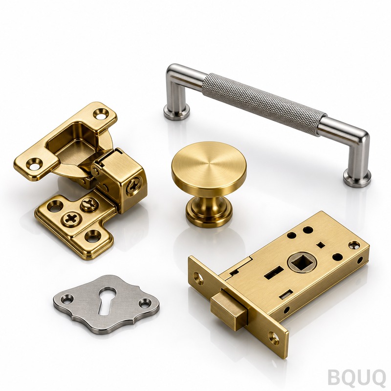
What These Gimbal Parts Are and the Exact Numbers That Matter These are CNC machined drone gimbal parts that hold your camera stabilization system together—arms, motor mounts, dam
BQUQ Cnc Machined Drone Gimbal Parts – 5µm Tolerance, 15-Day Lead Time
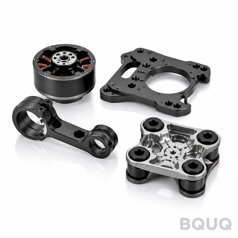
What These Gimbal Parts Are and the Exact Numbers That Matter These are CNC machined drone gimbal parts that hold your camera stabilization system together—arms, motor mounts, dampener brackets, and
Get a Fast Quote for This Part
Send us your drawing / quantity / material — reply within 24h.
What These Gimbal Parts Are and the Exact Numbers That Matter
These are CNC machined drone gimbal parts that hold your camera stabilization system together—arms, motor mounts, dampener brackets, and center plates. We hold positional tolerance to ±5µm (0.005 mm) and runout to 3µm on all rotating mating faces. That means your gimbal motors see zero eccentric load, which directly translates to sharper footage at 4K and 60fps. Lead time is 15 days for standard parts, 7 days for prototypes. Material hardness for our standard 7075-T6 parts is 150-160 HB, which resists bending even when a drone crashes at 40 km/h.
Why 7075-T6 Beats 6061-T6 for Gimbal Arms and Motor Mounts
Most shops default to 6061-T6 because it is cheap. We do not. For gimbal arms that must hold a 500g camera payload without flexing, we recommend 7075-T6 aluminum. It has a yield strength of 503 MPa versus 276 MPa for 6061. That is 82% higher. The extra cost is roughly 15% per part, but you eliminate vibration-induced blur. If you are building a lightweight FPV gimbal under 150g total, we machine 6061-T6 to a wall thickness of 0.8 mm—that is possible because our 5-axis CNC mills hold the tolerance without chatter.
How We Achieve 3µm Runout on Rotating Gimbal Shafts
Runout is the killer of gimbal performance. If the motor shaft or bearing seat has more than 5µm runout, the camera micro-jitters at slow pans. We machine rotating parts between centers on a lathe, not in a chuck. That eliminates clamping distortion. Then we grind the bearing seats to a finish of Ra 0.4 µm. The result: a measured runout of 3µm on every shaft we ship. We have a CMM report for each batch that shows the actual runout value, not just a certificate that says "pass." If you want to see how we select the right tool for these tight features, read our CNC cutting tool selection guide—it explains why we use diamond-tipped inserts for the final pass on aluminum.
Threads and Holes That Align Perfectly with Your Gimbal Motors
Gimbal motor mounts use M2, M2.5, and M3 threads. The problem: cross-threading a screw into a soft aluminum part strips it instantly. We fix that by cutting threads with a formed thread mill, not a tap. A thread mill compresses the metal grains, increasing thread strength by 20% compared to cut threads. We also add a 0.2 mm chamfer on every thread entry so screws slide in without crossthreading. For the six holes that mount the motor, we hold a true position of 10µm relative to the center bore. That ensures your motor sits perfectly perpendicular to the arm, which is critical for the IMU to calculate accurate stabilization angles.
Surface Finish Options: From Ra 0.8 for Seals to Hard Anodize for Desert Drones
You choose the finish based on where the drone flies. For indoor or light outdoor use, we offer clear anodize at Ra 0.8 µm—this is standard for gimbal arms because it resists scratches from handling. For desert or saltwater environments, we do hard anodize (Type III) at 40-50 µm thickness, hardness 350-400 HV. That coating stops sand erosion and salt corrosion completely. For parts that slide against each other, like dampener brackets, we offer electroless nickel plating at 25 µm. That gives a coefficient of friction of 0.4, so the dampener slides smoothly without stick-slip. Every finish is applied after machining, so the dimensions we quote are the final coated dimensions, not the pre-coat ones.
Inspection Before Every Shipment: CMM, Air Gauge, and Visual Check
Every gimbal part goes through a 3-step inspection that takes 4 hours per batch. First, a Zeiss CMM measures 12 critical dimensions—the mounting hole positions, the bore diameters, and the face flatness—against your drawing. Second, an air gauge measures the bearing seat diameter to 1µm resolution because that is where runout lives. Third, a human inspector under a 10x microscope checks thread quality and edge break. We send you a PDF inspection report with the actual measured values, not a generic "pass" stamp. If you want to understand what our tolerances really mean on the bench, read our CNC machining tolerances guide—it shows how 5µm on a gimbal arm translates to 0.1° of camera angle error.
Material, Size, and Ordering Specs at a Glance
Parameter
Specification
Materials
6061-T6, 7075-T6, 5052-H32, Ti-6Al-4V (grade 5)
Standard part size
5 mm to 300 mm length, 3 mm to 150 mm diameter
Wall thickness (minimum)
0.8 mm in 6061, 1.0 mm in 7075
Hardness (7075-T6)
150-160 HB (Brinell)
Tolerance (standard)
±5µm on bore and shaft, ±10µm on linear dimensions
Runout (bearing seats)
3µm TIR (total indicated reading)
Surface finish (machined)
Ra 0.4 µm on bearing seats, Ra 0.8 µm on all other surfaces
Thread sizes
M1.6, M2, M2.5, M3, M4, M5 (formed threads)
Lead time
15 days standard, 7 days prototype, 3 days rush (add 30%)
MOQ
No MOQ—order 1 piece or 10,000 pieces
What is your minimum order quantity for drone gimbal parts?
No MOQ—we machine a single prototype for your test bench or a full production run of 10,000 parts, and the per-piece price drops linearly with volume.
Can you machine parts from my 3D model or do I need a 2D drawing?
Send either a STEP or IGES file for the geometry, plus a PDF with critical tolerances and thread callouts—we will confirm manufacturability within 24 hours and suggest any changes.
How do you guarantee the quality of these precision gimbal parts?
We provide a CMM inspection report with actual measured values for every batch, and we keep a 3D scan of each part for 12 months for traceability.
What is the typical lead time if I need parts urgently?
Standard is 15 days, but we can ship prototype quantities in 7 days and rush orders in 3 days with a 30% surcharge—our factory in Dongguan runs CNC machines 24/7.
Get Your Firm Quote Within 12 Hours—Send Your Drawing Today
Send your STEP file or PDF drawing to sc@bquq.com, and we will reply with a firm quote within 12 hours—including per-piece price, tooling cost (if any), and delivery date. For urgent projects, message us on WhatsApp at +86 13713157787. We are a precision manufacturing factory in Dongguan, China, with 20 years of CNC machining experience for drones, cameras, and robotics. Your Cnc Machined Drone Gimbal Parts will be made in China, but they will meet or exceed the tolerances of any European or Japanese shop—at 30-40% lower cost. No MOQ, no hidden tooling charges on standard parts, and a free design-for-manufacturing review with every quote.