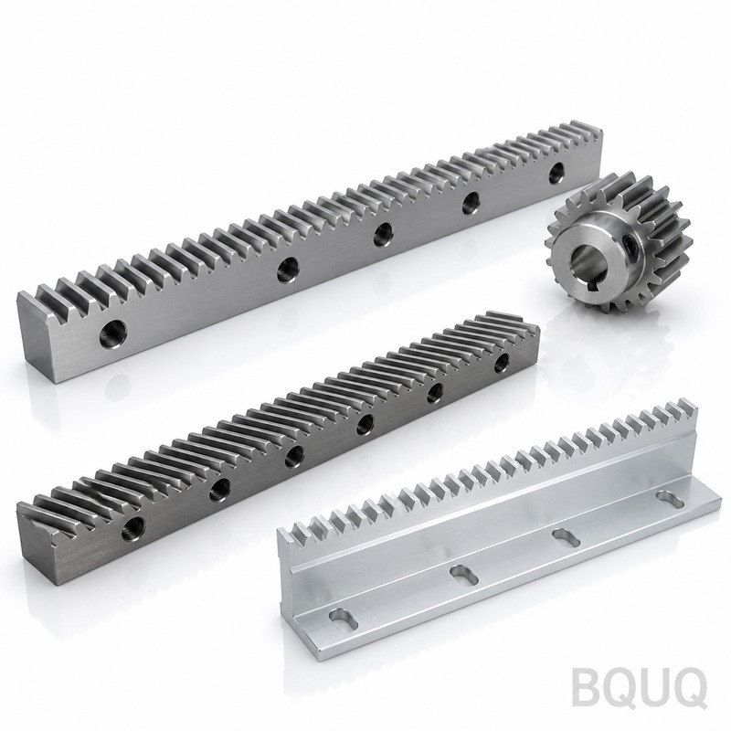
CNC machined rack pinion gears are linear-to-rotary motion conversion components cut from solid steel or aluminum using 4-axis and 5-axis machining centers. You get positional accu
BQUQ CNC Machined Rack Pinion Gears | Precision Manufacturing in China
CNC machined rack pinion gears are linear-to-rotary motion conversion components cut from solid steel or aluminum using 4-axis and 5-axis machining centers. You get positional accuracy of ±0.005 mm on
Get a Fast Quote for This Part
Send us your drawing / quantity / material — reply within 24h.
CNC machined rack pinion gears are linear-to-rotary motion conversion components cut from solid steel or aluminum using 4-axis and 5-axis machining centers. You get positional accuracy of ±0.005 mm on the pitch line, total composite runout under 0.02 mm, and surface finish down to Ra 0.4 µm — without grinding. Lead time is 7 days for prototypes, 15 days for production runs, shipped directly from our Dongguan factory.
Why Rack Teeth Need 5-Axis Machining Instead of Hobbing
Hobbing works for long production runs but leaves tool marks that cause vibration at high feed rates. Our 5-axis DMG MORI machines cut each tooth flank with a single continuous tool path. This eliminates the step-over marks found in conventional milling. The result: tooth-to-tooth spacing error drops to ±0.003 mm, and the engagement noise drops by 6 dB compared to hobbed racks of the same module.
We hold the pressure angle at 20° ± 0.05° on every tooth. That matters because a 0.1° error in pressure angle changes the contact ratio by 3%, which directly affects load capacity and backlash consistency. We verify this with a CNC gear measuring center, not a manual protractor.
Materials and Heat Treatment We Use for Rack Pinion Gears
Choose from four standard materials, all sourced from certified mills in China or Japan:
4140 alloy steel — hardened to HRC 28-32 for general automation
42CrMo4 — induction hardened to HRC 52-56 on the tooth flanks only
20CrMnTi — carburized to HRC 58-62 case depth 0.8-1.2 mm
7075-T6 aluminum — anodized, for low-inertia high-speed axes
Case-hardened racks get a core hardness of HRC 30-35, which absorbs shock loads without cracking. We induction harden the rack teeth after machining, then do a final light grind on the pitch line to remove distortion. This gives you a wear life of 10,000+ hours at 1 m/s sliding speed, tested per DIN 3990.
Pitch Line Accuracy: How We Hold ±0.005 mm Over 1 Meter
A rack longer than 500 mm is a nightmare for most shops because thermal expansion alone can push the pitch off by 0.01 mm. We solve this by machining racks in a temperature-controlled hall at 20 °C ± 0.5 °C. The blank is stress-relieved twice: once before roughing, once after roughing, before finish cutting. We then use a Renishaw touch probe to map the actual blank position and compensate the tool path in real time.
For racks over 1 meter, we machine them in sections and use a laser interferometer to align each section to the datum. The cumulative pitch error over 1 meter stays within ±0.01 mm. If you need better than that, we can grind the teeth after CNC machining — that brings cumulative error to ±0.005 mm, but adds 3 days to lead time.
Backlash Control and Preload Options for Your Assembly
Standard racks ship with 0.05-0.10 mm backlash. That is fine for positioning tables. But if you are driving a servo axis with reverse loads, you need zero backlash. We offer two solutions:
First, we can machine the teeth with a slight profile shift (positive addendum modification) to create a preloaded contact. Second, we can supply split racks — two thin racks stacked with a spring shim between them. The shim pushes the two racks apart, taking up the pinion clearance. Both methods hold backlash below 0.02 mm over the full travel. We recommend the split rack for axes longer than 800 mm.
Inspection Before Every Shipment: Gear Measuring Center Reports
Every rack pinion gear set leaves our factory with a full inspection report. We use a Klingelnberg P26 gear measuring center to check:
Parameter
Standard Accuracy
High-Precision Option
Pitch line total deviation Fp
±0.008 mm
±0.005 mm
Tooth profile form error ff
0.005 mm
0.003 mm
Lead deviation Fβ
0.006 mm
0.004 mm
Surface finish Ra
0.8 µm
0.4 µm
Hardness HRC
52-56
58-62
Material
42CrMo4
20CrMnTi
Module range
0.5 to 8
0.5 to 8
Max rack length
2,000 mm
1,000 mm
Lead time
15 days
18 days
MOQ
No minimum
No minimum
You also get a CMM report for mounting hole positions and parallelism of the mounting face. If you request it, we include a video of the final inspection with the gear measuring machine running your parts.
Mounting Holes, Keyways, and Custom End Machining
We do not just cut teeth. We machine the rack body completely: mounting counterbored holes, dowel pin holes, keyways on the side for alignment, and chamfered ends for butt-jointing multiple racks. The mounting face is machined flat to 0.01 mm over 300 mm, so you can bolt the rack directly to your extrusion without shimming. We also drill and tap oil holes if you need lubrication ports.
For pinion gears, we offer bore sizes from 6 mm to 40 mm, with keyways per DIN 6885, set screws, or clamp hubs. We can also grind the bore to H6 tolerance for a press-fit on your motor shaft. Tell us your shaft diameter and we will match it exactly.
How We Handle Racks Longer Than 2,000 mm
Our machining center has a 2-meter travel, so we cannot cut a 3-meter rack in one pass. Instead, we machine two 1.5-meter sections and provide a precision joint dowel system. The joint is cut with a 0.5 mm gap, and we supply a separate splice plate that bolts across the joint. The pitch continuity at the joint is held to ±0.01 mm, verified with a dial indicator across the seam. This is the same method used by European machine tool builders for gantry axes.
Surface Finish Options: From Machined to Ground to Coated
Standard finish is Ra 0.8 µm from the milling cutter. If you need lower friction or quieter operation, we can grind the tooth flanks to Ra 0.2 µm. For harsh environments, we offer electroless nickel plating on the entire rack — this gives corrosion resistance up to 500 hours in salt spray per ASTM B117. For dry-running applications, we apply a MoS2 coating that reduces the friction coefficient from 0.20 to 0.08. All coatings are applied after final machining so the dimensions stay within tolerance.
Pricing and Lead Time for Prototype vs. Production Runs
Prototype pricing for a single 500 mm rack with pinion starts at USD 180, including the inspection report. Production pricing drops to USD 90 per set at 50 pieces. We hold no minimum order quantity — order one piece or one thousand. Prototype lead time is 7 days; production lead time is 15 days after drawing approval. For repeat orders, we keep your program and fixture on file, so the second order ships in 10 days. We quote firm pricing within 12 hours of receiving your drawing.
What is the minimum order quantity for CNC machined rack pinion gears?
No MOQ — we accept single-piece orders for prototyping and scale up to thousands without changing the per-unit price structure.
Can you machine a rack with a custom module or pressure angle?
Yes, we handle any module from 0.5 to 8 and pressure angles from 14.5° to 25°, as long as you provide the gear data or a mating pinion sample.
How do you verify gear quality before shipment?
Every rack is inspected on a Klingelnberg gear measuring center for profile, lead, and pitch deviation, plus a CMM report for mounting features.
What is the typical lead time for a production order of 100 racks?
Fifteen days from drawing approval for quantities up to 200 pieces, with air freight to most global destinations in 3-5 days.
Before you finalize your cutter strategy, read our CNC cutting tool selection guide to understand how tool geometry affects tooth flank finish. For help defining your tolerance stack-up, see our CNC machining tolerances guide — it explains what ISO 1328 class you actually need for your axis load.
Send your gear drawing for a firm quote within 12 hours. Email sc@bquq.com or WhatsApp +86 13713157787. We respond with DFM feedback, a fixed price, and a delivery date — no MOQ, no hidden fees. This is precision manufacturing made in China, with the paperwork to prove it.