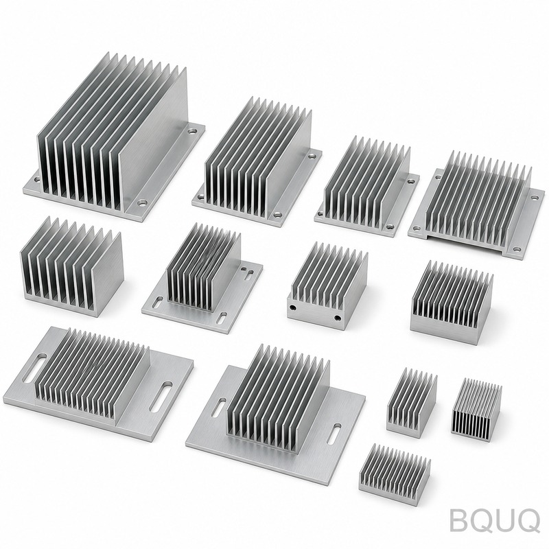
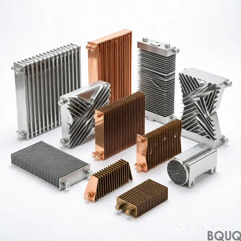
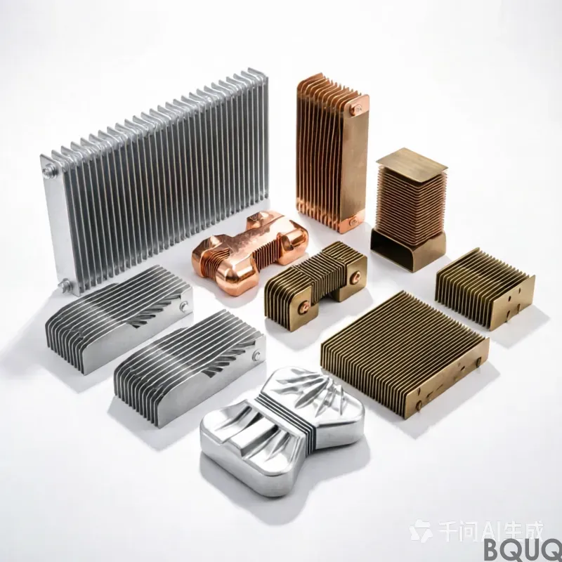
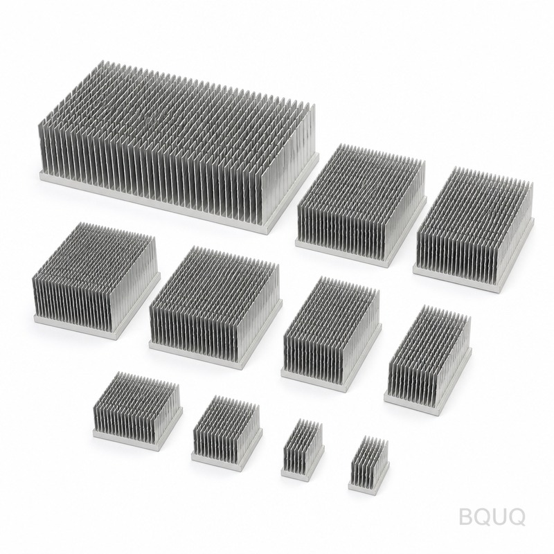
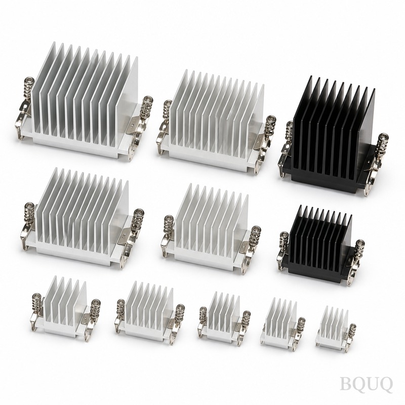
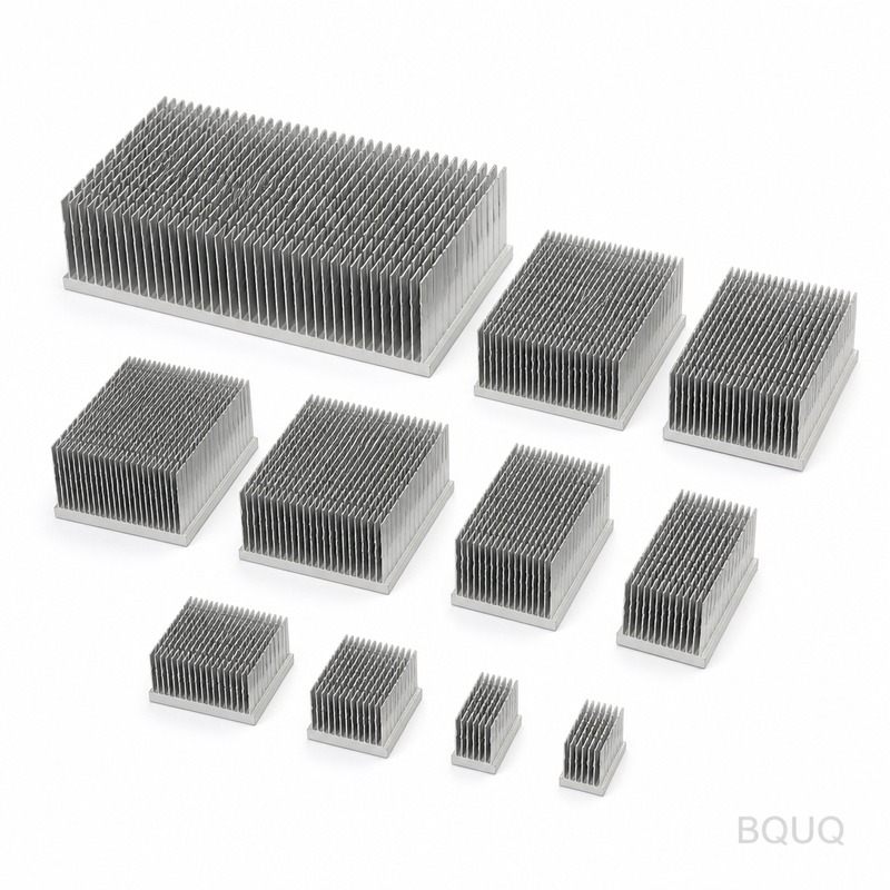
Extruded Aluminum Heatsink Collection 02 is a family of 12 standard profiles engineered for forced-air and natural convection cooling of IGBT modules, power supplies, and LED drive
Extruded Aluminum Heatsink Collection 02 is a family of 12 standard profiles engineered for forced-air and natural convection cooling of IGBT modules, power supplies, and LED drivers. Each profile shi
Get a Fast Quote for This Part
Send us your drawing / quantity / material — reply within 24h.
Extruded Aluminum Heatsink Collection 02 is a family of 12 standard profiles engineered for forced-air and natural convection cooling of IGBT modules, power supplies, and LED drivers. Each profile ships with a flatness tolerance of 0.05 mm per 100 mm length and a surface finish of Ra 1.6 µm, so you can bolt components directly without lapping or thermal pad thickness compensation.
These heatsinks are precision manufacturing products made in China by BQUQ, a 20-year factory specializing in CNC machining, stamping, and springs. Lead time for standard profiles is 15 days from order confirmation, and we offer 60 HRC hard anodizing as an option for abrasive environments.
Profile Geometry and Fin Spacing That Match Real Airflow
Collection 02 covers fin heights from 15 mm to 45 mm, base thicknesses from 4 mm to 10 mm, and fin pitches of 5 mm, 7 mm, and 10 mm. The 5 mm pitch profiles are designed for high static pressure fans; the 10 mm pitch profiles suit natural convection or low-rpm axial fans.
All profiles are extruded from 6063-T5 aluminum, which gives a thermal conductivity of 209 W/m·K. We keep the extrusion die tolerance at ±0.1 mm on fin thickness and ±0.15 mm on overall width. This means you can predict thermal resistance within ±5% without running your own CFD.
CNC Finishing: Cut Length, Holes, and Threads in One Setup
Raw extrusion is only the start. Each heatsink in Collection 02 is cut to your specified length with a saw tolerance of ±0.2 mm, then machined on 3-axis CNC centers if you need mounting holes, tapped threads, or counterbores. We hold hole position tolerance at 0.05 mm and thread depth at ±0.3 mm.
If you are unsure about tool geometry for these aluminum extrusions, check our CNC cutting tool selection guide before finalizing your drawing. For hole-to-hole and datum tolerances, our CNC machining tolerances guide explains what we can hold without driving up cost.
Hard Anodizing Up to 60 HRC for Abrasive Installations
Standard finish is clear anodize to MIL-A-8625 Type II, 10–15 µm thickness. If your assembly process involves repeated bracket sliding or vibration against steel parts, we apply hard anodizing Type III to 40–60 HRC on the base surface only. This does not reduce thermal performance measurably; the coating adds less than 0.05 °C/W resistance.
We also offer a chromate conversion coating (Alodine) for electrical grounding requirements. No coating is applied inside tapped holes unless specified, because we re-tap after anodizing anyway to restore thread class 2B.
Cut-to-Length with No MOQ and 15-Day Standard Lead Time
You can order one piece or one thousand pieces. The no MOQ policy applies to every profile in Collection 02. Standard lead time is 15 days for cut-to-length with no machining, 18 days for CNC holes and threads, and 21 days if hard anodizing is required. For urgent orders, we can pull stock profiles and ship within 7 days.
All profiles are stocked as 3-meter bars in our Dongguan warehouse. We cut to your exact length, deburr all edges, and clean the parts before packaging with foam separators to prevent fin damage during shipping.
Inspection Report and Dimensional Check Before Every Shipment
Every batch, regardless of quantity, gets a full inspection. We measure flatness on a granite table with a dial indicator, check fin height with calipers, verify hole positions with a CMM for orders above 50 pieces, and record surface roughness with a profilometer on the base.
You receive a PDF inspection report with actual measured values, not just a pass/fail mark. For orders above 200 pieces, we include a process capability index (Cpk) for critical dimensions if requested at quote stage.
Specification
Value
Material
6063-T5 aluminum extrusion
Available profiles
12 fixed fin geometries
Fin height range
15 mm – 45 mm
Base thickness
4 mm – 10 mm
Fin pitch
5 mm / 7 mm / 10 mm
Length tolerance (cut)
±0.2 mm
Flatness (per 100 mm)
0.05 mm
Surface finish (base)
Ra 1.6 µm (as machined)
Hard anodizing hardness
40–60 HRC (optional)
Coating thickness
10–15 µm Type II / 25–50 µm Type III
Lead time (standard)
15 days
Minimum order
No MOQ
How to Choose the Right Profile from Collection 02
If your heat source is smaller than 40% of the base footprint, pick a profile with thicker base (8 mm or 10 mm) to spread heat before it reaches the fins. If your airflow is limited, pick the 10 mm fin pitch to reduce pressure drop. If you have a high-power IGBT with forced air above 3 m/s, the 5 mm pitch profile will give the lowest thermal resistance per unit length.
We can also modify any profile by removing fins near mounting holes or adding a step in the base. This is a quick CNC operation that does not extend lead time beyond 18 days.
Packaging and Shipping That Protects Fins on Long Parts
Parts longer than 300 mm are packed in rigid cardboard boxes with foam channel inserts that match the fin profile. We do not use loose bubble wrap because it can bend thin fins during transit. For international air freight, we use wooden crates for orders above 20 kg. For sea freight, we use moisture-barrier bags with desiccant.
Every box is labeled with the profile number, length, quantity, and your PO number. We can include custom labels or barcodes if required for your warehouse system.
Cost Drivers and How to Reduce Your Unit Price
The base price of Collection 02 is set by extrusion weight and cut length. CNC holes add a fixed setup cost per batch, not per hole. Hard anodizing adds about 8% to the unit price. If you order the same profile and length every month, we can hold a buffer stock for you and ship within 5 days, which also reduces the per-unit price by 3%.
For a quick price estimate, send your length, hole pattern, and annual quantity. We respond with a firm quote within 12 hours, including tooling cost if you need a new extrusion die.
Standard Profiles List and Intended Applications
Profiles 02-01 through 02-04 are low-profile (15–20 mm fin height) for LED drivers and DC-DC converters. Profiles 02-05 through 02-08 are mid-height (25–30 mm) for MOSFET bridges and servo drives. Profiles 02-09 through 02-12 are tall (35–45 mm) with thick bases for IGBT modules and high-power rectifiers.
All profiles have a mounting slot option (3 mm wide, 6 mm deep) on the base for spring clips. If you use thermal adhesive instead of screws, we can supply a milled flat surface with Ra 0.8 µm for better contact.
What is the minimum order quantity for Extruded Aluminum Heatsink Collection 02?
There is no MOQ — you can order a single cut length for prototyping or a full production batch.
Can you customize hole patterns or fin lengths on these heatsinks?
Yes, any profile can be CNC machined with custom holes, threads, counterbores, or step cuts, and we hold position tolerance at 0.05 mm.
How do you control quality on small batches?
Every batch, even one piece, gets a full dimensional inspection and you receive a PDF report with measured values for flatness, length, and hole positions.
What is the actual lead time if I need hard anodizing?
Standard lead time is 15 days for cut-to-length, 18 days with CNC machining, and 21 days if you add Type III hard anodizing.
Get a firm quote within 12 hours. Email your drawing to sc@bquq.com or send it via WhatsApp to +86 13713157787. We will reply with unit price, tooling cost (if any), and confirmed lead time. Send your drawing now.