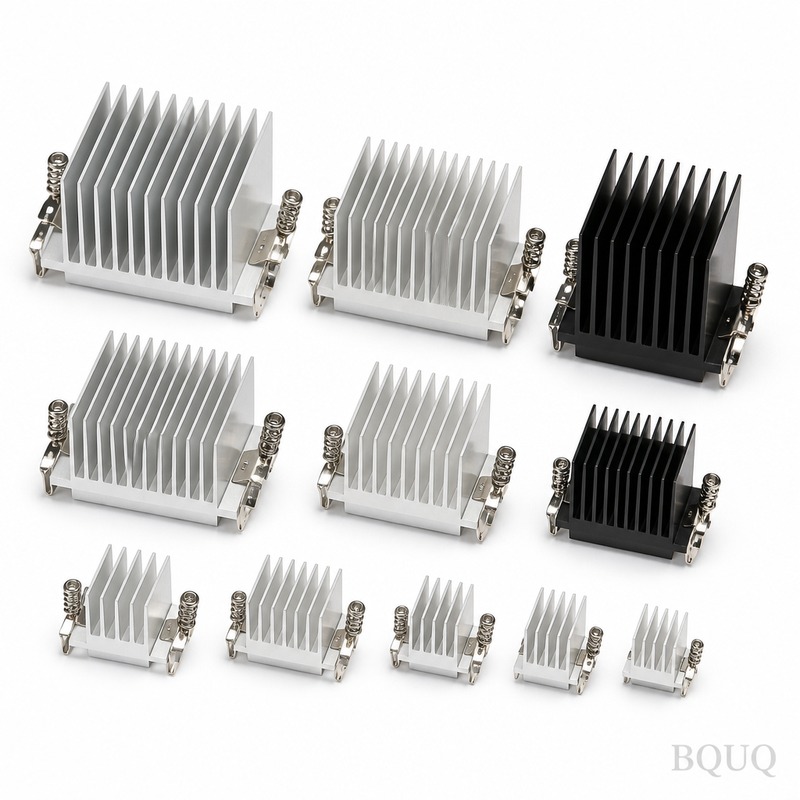
This High Power IGBT Heat Sink is a CNC-machined aluminum or copper base plate designed to pull 300 W to 2,500 W of heat away from IGBT modules in inverters, motor drives, and EV c
High Power IGBT Heat Sink | BQUQ Precision CNC Machining, Made in China
This High Power IGBT Heat Sink is a CNC-machined aluminum or copper base plate designed to pull 300 W to 2,500 W of heat away from IGBT modules in inverters, motor drives, and EV chargers. You get a f
Get a Fast Quote for This Part
Send us your drawing / quantity / material — reply within 24h.
This High Power IGBT Heat Sink is a CNC-machined aluminum or copper base plate designed to pull 300 W to 2,500 W of heat away from IGBT modules in inverters, motor drives, and EV chargers. You get a flatness tolerance of 0.02 mm across the mounting surface, a 5-day lead time for prototypes, and a surface hardness of 45 HRC when hard-anodized. It is precision manufacturing from BQUQ, made in China, with no MOQ for your first order.
CNC Machined Base Plate Flatness for Maximum IGBT Contact
The mounting surface is machined on a 5-axis CNC center to a flatness of 0.02 mm over 300 mm length. This prevents air gaps between the IGBT module and the heat sink, which is critical because even a 0.05 mm gap can raise junction temperature by 15°C. We use a single-point diamond fly cutter to achieve a surface finish of Ra 0.8 µm. This is not a stamped or extruded part—every fin and channel is milled from solid 6061-T6 aluminum or C1100 copper.
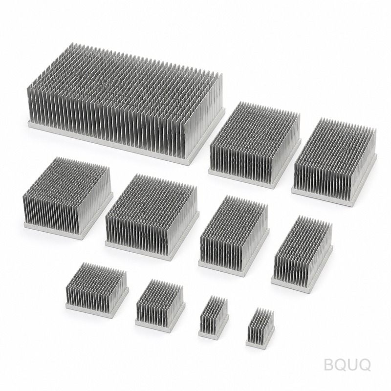
Pin Fin and Channel Fin Geometry for 2,500 W Dissipation
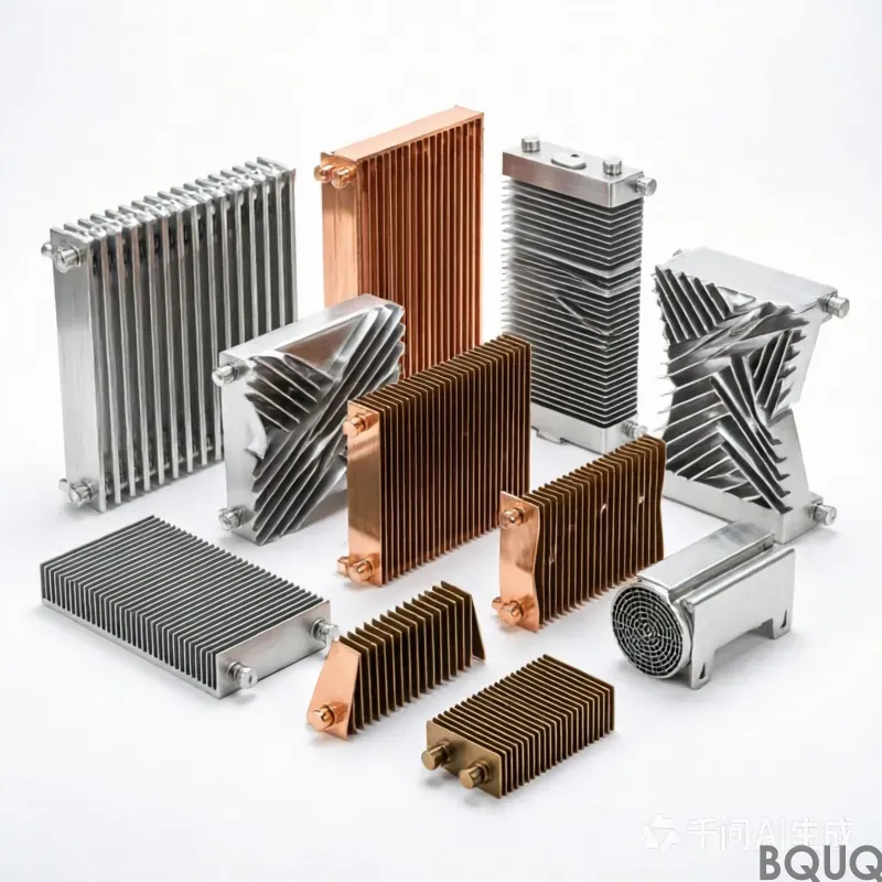
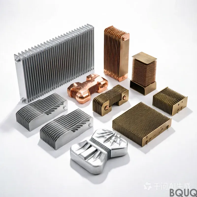
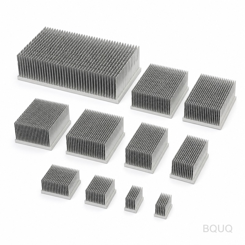
Choose between pin fin arrays (3 mm diameter, 8 mm pitch) for omnidirectional airflow or straight channel fins (2.5 mm wide, 12 mm deep) for ducted cooling. Our thermal simulation shows a thermal resistance of 0.05 °C/W for a 300 mm x 300 mm copper pin fin version. For higher power, we machine a vapor chamber slot into the base plate—depth accuracy is ±0.05 mm. The fin height can go up to 80 mm without deformation, thanks to our 12,000 RPM spindle and rigid fixturing.
Hard Anodizing to 45 HRC with 25 µm Coating Thickness
We apply Type III hard anodizing to the aluminum version, which gives a surface hardness of 45 HRC and a dielectric breakdown voltage of 800 V. The coating thickness is 25 µm ± 5 µm, measured with an eddy current gauge on every batch. This layer resists corrosion in salt spray tests for 336 hours (ASTM B117). For copper versions, we apply a nickel-plated finish—5 µm thick—to prevent oxidation and maintain solderability for direct IGBT mounting.
Threaded Inserts and Mounting Holes with True Position 0.05 mm
We pre-install stainless steel threaded inserts (M4, M5, M6) for IGBT module screws. The true position of these holes is held to 0.05 mm, so your module aligns perfectly without stress on the DBC substrate. Counterbore depths are controlled to ±0.03 mm to ensure screw heads sit flush. If you use through-holes instead, we deburr both sides with a 0.2 mm chamfer—no sharp edges that can cut cable insulation during assembly.
Prototype to Production in 5 Days, No MOQ Required
Send a STEP or IGES file, and we machine a single prototype in 5 days. Because this is precision manufacturing with no MOQ, you can order just one unit for testing or 10,000 units for production. Our factory in Dongguan runs 24/7 with 40 CNC machines, so we batch your parts with similar heat sinks to reduce cost. For a 200 mm x 200 mm aluminum pin fin heat sink, the unit price drops from $45 (qty 1) to $18 (qty 500).
Material Traceability and Thermal Testing Report
Every heat sink ships with a material certificate (EN 10204 3.1) confirming 6061-T6 aluminum or C1100 copper composition. We also include a thermal resistance test report measured on our custom test rig—not just a simulation. The report shows temperature rise at 50 W, 100 W, and 200 W with a 0.5 m/s airflow. This data helps your thermal engineer validate system performance without running your own tests. We keep a sample of each batch for 12 months for traceability.
Surface Finish Options for Different Mounting Methods
If you solder the IGBT directly to the heat sink, we provide a bare copper surface with Ra 0.4 µm and a flatness of 0.01 mm—solder voids are reduced to under 2% as verified by X-ray inspection. If you use thermal paste, we apply a matte bead-blasted finish (Ra 1.6 µm) that increases paste adhesion and prevents pump-out. For clip mounting, we machine a dovetail groove with a 0.02 mm parallelism tolerance. All options are available on the same base design—just specify in your drawing.
Specification
Value
Notes
Material
6061-T6 Aluminum / C1100 Copper
Other alloys on request
Base Plate Size
50 x 50 mm to 600 x 400 mm
Custom sizes no extra tooling
Fin Height
Up to 80 mm
Pin or straight fin
Flatness (Mounting Surface)
0.02 mm over 300 mm
Measured on granite plate
Surface Finish
Ra 0.4 µm to 1.6 µm
Depends on mounting method
Hard Anodize Thickness
25 µm ± 5 µm
45 HRC hardness
Threaded Inserts
M3 to M8, stainless steel
True position 0.05 mm
Tolerance (General)
±0.02 mm
Hole positions ±0.05 mm
Lead Time (Prototype)
5 days
Production 15-20 days
MOQ
No minimum
Single piece accepted
Finite Element Analysis (FEA) Validation for Your Specific IGBT Module
Before we cut metal, our thermal engineer runs a steady-state FEA simulation using your IGBT power loss, coolant flow rate, and ambient temperature. We model the junction-to-case thermal resistance and adjust fin density and base thickness accordingly. For example, a 600 V/600 A IGBT module with 1,200 W loss needs a copper base thickness of 12 mm and a fin pitch of 6 mm—we give you this recommendation in the quote. This service is free for all inquiries, and the FEA report is included with the final heat sink.
What is the maximum junction temperature this heat sink can handle?
With a 0.05 °C/W thermal resistance and forced air at 3 m/s, you can keep IGBT junction temperature below 125°C even at 1,500 W continuous power.
Can you machine a heat sink for a custom IGBT module footprint?
Yes, we machine any footprint from your 2D or 3D drawing, including non-standard hole patterns and odd base plate shapes.
Do you provide thermal paste or mounting clips with the heat sink?
We do not supply consumables, but we machine dovetail grooves or clip slots to your specified spring clip dimensions.
How do you ensure the heat sink is flat after anodizing?
We stress-relieve the aluminum before machining and apply a final skim cut after anodizing to restore the 0.02 mm flatness, which is verified on a granite table.
Get a Firm Quote with Thermal Simulation Within 12 Hours
Send your drawing or IGBT module datasheet to sc@bquq.com or WhatsApp +86 13713157787. We will respond within 12 hours with a firm unit price, lead time, and a preliminary thermal simulation result. For best results, reference our CNC cutting tool selection guide to specify your fin finish, and check our CNC machining tolerances guide to define your flatness and hole position requirements. No MOQ, no minimum order quantity—just send your drawing and we will start the precision manufacturing process today.