5 Optical Inspection Methods for Precision Manufacturing in 2024: Tolerances, Costs, and Throughput
5 Optical Inspection Methods for Precision Manufacturing in 2024: Tolerances, Costs, and Throughput
For precision manufacturing, optical inspection is the fastest non-contact method to verify dimensional accuracy, surface defects, and geometric features down to ±0.002 mm. In 2024, the five dominant optical techniques are machine vision (2D), laser triangulation (3D), white light interferometry (WLI), structured light scanning, and confocal microscopy. Each method has a specific tolerance band, cycle time, and cost profile, and choosing the wrong one can add 15-30% to your quality assurance overhead. This article breaks down the technical specifications and real-world pricing so you can select the right optical inspection system for your CNC-machined, stamped, or spring-manufactured components.
1. Machine Vision (2D) - The Workhorse for High-Speed Dimensional Checks
Machine vision systems using CCD or CMOS cameras with telecentric lenses remain the most cost-effective optical inspection method for production lines. They excel at measuring 2D features like hole diameters, edge positions, and overall part dimensions.
**Key Specifications:** - **Resolution:** 1-10 megapixels, with sub-pixel algorithms achieving accuracy of ±0.005 mm under ideal lighting - **Field of View:** 5 mm to 200 mm, depending on lens selection - **Inspection Speed:** 0.1 to 0.5 seconds per part, making them ideal for inline 100% inspection - **Typical Cost:** USD 8,000 to USD 45,000 for a complete turnkey station including lighting, optics, and software
A well-calibrated 2D vision system with backlight illumination can detect edge cracks as small as 0.03 mm on stamped parts. However, it cannot measure depth or z-axis features, which limits its use to flat or prismatic components.
2. Laser Triangulation - Precision 3D Profiling at Production Speeds
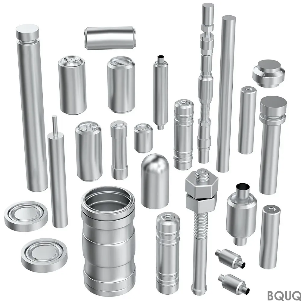
Laser triangulation sensors project a laser line onto the part surface and use a camera to detect the reflected angle, calculating height profiles with micron-level resolution. This method is widely used for measuring spring pitch, thread profiles, and machined surface contours.
**Key Specifications:** - **Z-Axis Resolution:** 0.002 mm to 0.010 mm, depending on sensor model - **Sampling Rate:** Up to 10,000 profiles per second (e.g., Keyence LJ-X8000 series) - **Measurement Range:** 5 mm to 500 mm in Z-axis - **Temperature Stability:** ±0.02% of full scale over 10-40°C - **Typical Cost:** USD 15,000 to USD 60,000 per sensor head plus controller
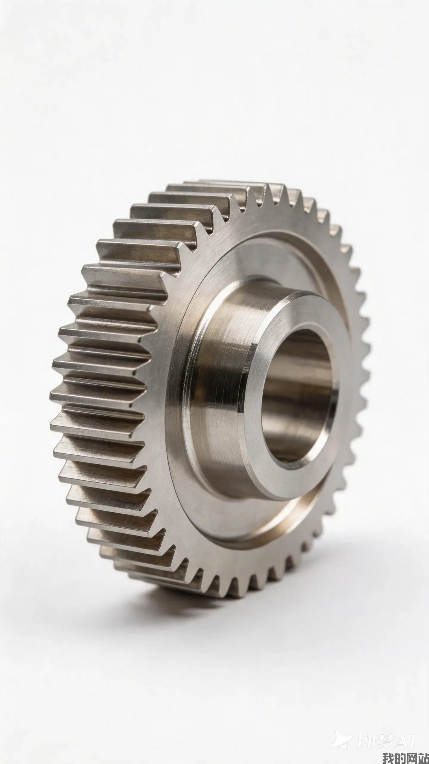
For a CNC machining shop producing aluminum housings, a laser triangulation system can verify flatness within 0.010 mm and detect burrs as small as 0.05 mm at a rate of 50 parts per minute. The main drawback is sensitivity to reflective surfaces; anodized or polished parts may require a diffuse spray or angle adjustment.
3. White Light Interferometry (WLI) - Nanometer-Level Surface Finish Analysis
When surface roughness (Ra) and micro-scale defects matter, white light interferometry is the gold standard. WLI uses a broadband light source split into two paths—one reflecting off the sample, one off a reference mirror—to create interference fringes that map surface topography.
**Key Specifications:** - **Vertical Resolution:** 0.01 nm (0.00001 mm) with sub-nanometer repeatability - **Lateral Resolution:** 0.3 µm to 1.0 µm, depending on objective lens - **Measurement Area:** 0.1 mm x 0.1 mm to 5 mm x 5 mm per frame - **Measurement Time:** 5-30 seconds per scan - **Typical Cost:** USD 50,000 to USD 180,000 for a benchtop system (e.g., Zygo, Bruker)
WLI is essential for validating the surface finish of heat sink bases (required Ra 0.8 µm or better) or the micro-texture of spring contact points. A single scan can quantify Ra, Rz, Rq, and reveal scratches deeper than 0.1 µm that would cause premature fatigue failure. Due to its slow speed, WLI is reserved for first-article inspection (FAI) and periodic audit sampling, not inline 100% checks.
4. Structured Light Scanning - Fast Full-Field 3D for Complex Geometries
Structured light scanners project a grid or fringe pattern onto the part and capture its deformation with one or two cameras, reconstructing a full 3D point cloud in seconds. This method is ideal for freeform surfaces, turbine blades, and complex stamped brackets.
**Key Specifications:** - **Accuracy:** ±0.010 mm to ±0.050 mm (industrial grade, e.g., GOM ATOS Q) - **Point Density:** Up to 12 million points per scan - **Scan Time:** 1-5 seconds per view, with automated turntables enabling full part coverage in under a minute - **Blue Light Technology:** Reduces ambient light interference, enabling measurement on glossy surfaces - **Typical Cost:** USD 60,000 to USD 150,000 for a complete system with software
Structured light excels at detecting warpage on large stamped panels (e.g., 300 mm x 300 mm) within ±0.03 mm, and it can generate a full color deviation map against the CAD model in real time. It requires a stable environment; vibrations above 5 Hz can degrade accuracy.
5. Confocal Microscopy - High Magnification for Micro-Features and Deep Bores
Confocal microscopy uses a pinhole to eliminate out-of-focus light, achieving high-resolution imaging of steep slopes, deep recesses, and micro-features that other optical methods miss. It is the preferred tool for inspecting EDM holes, micro-milled channels, and deburring quality.
**Key Specifications:** - **Magnification Range:** 100x to 10,000x - **Vertical Resolution:** 0.005 mm (5 µm layers) with focus stacking - **Depth of Field:** Up to 25 mm for deep bore inspection with a borescope adapter - **Working Distance:** 0.3 mm to 30 mm, depending on objective - **Typical Cost:** USD 40,000 to USD 120,000
For a spring manufacturer verifying the internal diameter of a 0.5 mm wire coil, confocal microscopy resolves the inner edge profile with ±0.003 mm accuracy. It is slower than laser methods (1-3 minutes per feature) but provides unmatched clarity for failure analysis and process validation.
Comparative Data Table: Optical Inspection Methods at a Glance
| Method | Accuracy (µm) | Speed (parts/min) | Max Part Size | Best For | Cost Range (USD) | ------------------------ | --------------- | ------------------- | --------------- | ------------------------------ | ------------------ | Machine Vision (2D) | ±5 | 120-600 | 200 mm | Holes, edges, flat parts | 8k-45k | Laser Triangulation | ±2-10 | 30-50 (profiles) | 500 mm | Profiles, threads, warpage | 15k-60k | White Light Interferometry | ±0.01 (vertical) | 2-10 (per scan) | 5 mm | Surface finish, Ra | 50k-180k | Structured Light | ±10-50 | 5-20 | 1000 mm | Freeform, large panels | 60k-150k | Confocal Microscopy | ±3 (lateral) | 0.3-1 | 100 mm | Micro-features, bores | 40k-120k |
|---|
Practical Recommendations for Your Factory Floor
**Select by tolerance, not by price.** If your print calls for ±0.01 mm on a critical bore, machine vision will fail even with a high-end lens. Invest in laser triangulation or structured light for that line. Conversely, do not buy a USD 100,000 WLI system if your tightest tolerance is ±0.05 mm—a USD 30,000 laser scanner will suffice and run 10x faster.
**Combine methods for 100% inspection.** Use machine vision for inline screening of every part (catches gross errors in 0.2 seconds), then route one part per hour to a WLI or confocal station for surface and micro-feature validation. This hybrid approach cuts escaped defects by up to 70% while keeping inspection cost per part under USD 0.50.
**Control environmental factors.** All optical methods are sensitive to temperature gradients and vibration. Maintain a metrology room at 20±1°C for WLI and confocal. For inline laser and vision systems, mount them on vibration-isolated frames and use air curtains to prevent dust from creating false readings.
**Calibrate weekly with traceable standards.** Use a certified gauge block (Grade 0, tolerance ±0.00025 mm) to verify your optical system's accuracy every Monday morning. Drifts of more than 2 µm in 2D systems or 5 µm in 3D systems indicate lens contamination or thermal expansion issues.
FAQ: Common Pitfalls and Quick Tips
**Q: Why does my optical system show different results than my CMM?** A: Optical methods measure the outer surface (reflected light), while a CMM touches the physical point. On a rough surface (Ra > 1.6 µm), optical readings can be 2-5 µm higher. Always specify the measurement method on the drawing.
**Q: How do I inspect black anodized aluminum parts?** A: Use blue light structured scanning or apply a thin developer spray (e.g., Helling) to create a diffusive coating. Laser triangulation struggles on matte black surfaces due to absorbed light.
**Q: What is the minimum detectable defect for each method?** A: Machine vision: 0.03 mm edge crack; Laser: 0.05 mm height step; WLI: 0.01 µm scratch depth; Structured light: 0.1 mm surface deviation; Confocal: 0.5 µm lateral feature.
Conclusion: Match the Method to the Feature
Optical inspection is not a one-size-fits-all solution. For 90% of precision manufacturing tasks, a combination of machine vision (for speed) and laser triangulation (for depth) covers your needs under USD 70,000. Reserve WLI and confocal for surface finish and micro-feature validation where their nanometer resolution justifies the higher price. The key is to define your critical tolerances, part volume, and budget first, then select the optical method that hits all three targets.
By implementing the right optical inspection strategy, you can reduce false rejects by 30%, catch defects before they reach customers, and maintain the ±0.005 mm tolerances that modern aerospace, automotive, and medical clients demand.
---
**Need help selecting or implementing an optical inspection system for your precision parts?**
At BQUQ Precision Manufacturing (Dongguan, China), we have 20 years of experience machining, stamping, and forming components to tolerances as tight as ±0.005 mm. Our in-house quality lab uses all five optical inspection methods described above, and we provide free measurement reports with every order.
Get a 12-hour quote with full inspection specifications by contacting our engineering team: - Email: sc@bquq.com - WhatsApp: +86 13713157787 - Web: www.bquq.com
Send us your drawings today, and we will confirm the optimal inspection method for your critical dimensions.
Related Articles
- 5 Benefits of CNC Precision Turned Parts for Aerospace
- CNC Machine Maintenance Guide for Maximum Uptime: 2025 Calibration Schedule
- Aluminum Heat Sink CNC Machining: Best Practices Guide
Frequently Asked Questions
What is the fastest optical inspection method for inline 100% inspection of flat parts?
Machine vision (2D) is the fastest, with inspection speeds of 0.1 to 0.5 seconds per part. It is ideal for inline 100% inspection of flat or prismatic components, measuring features like hole diameters and edge positions with accuracy of ±0.005 mm under ideal lighting.
Which optical method can measure depth or z-axis features like spring pitch and thread profiles?
Laser triangulation is the method for 3D profiling, measuring z-axis features with resolution of 0.002 mm to 0.010 mm. It can verify flatness within 0.010 mm and detect burrs as small as 0.05 mm at rates up to 50 parts per minute, making it suitable for spring pitch and thread profiles.
What are the typical costs for a machine vision system and a laser triangulation system?
A complete turnkey machine vision station costs USD 8,000 to USD 45,000, including lighting, optics, and software. A laser triangulation system costs USD 15,000 to USD 60,000 per sensor head plus controller, depending on the model and specifications.
What is the minimum defect size that a 2D vision system can detect on stamped parts?
A well-calibrated 2D vision system with backlight illumination can detect edge cracks as small as 0.03 mm on stamped parts. However, it cannot measure depth or z-axis features, limiting its use to flat or prismatic components.